LEDs are fairly straightforward to use — just put them in series with a current-limiting resistor and apply forward voltage to produce light of whatever color the LED is designed for.
What isn’t as well-known, though, is that LEDs can also be used as photodetectors, sensitive to the color of light that they emit. This is a somewhat nonstandard use of an LED, but requires no more components than a standard blinking-LED project — an LED, a current-limiting resistor, and a microcontroller.
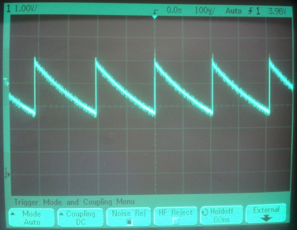
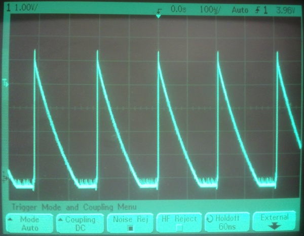
The trick is to run the LED backwards, reverse-biasing it for a short time (a microsecond is more than enough) — then disconnect the input (tristating the microcontroller I/O pin), and time how long it takes for the voltage to be reduced to below the TTL low threshold. Some leakage current will flow across the LED even in darkness, lowering the voltage towards zero with a time constant on the order of perhaps a few hundred microseconds. When brightly illuminated with light of the correct wavelength, however, a much greater photocurrent will flow, lowering the voltage on the pin in a few tens of microseconds.
In practice, this allows for a fairly straightforward recipe for detecting bright light of the LED’s wavelength (or shorter):
- Connect the cathode (negative lead) of the LED to an I/O pin
- Connect the anode (positive lead) of the LED to Ground via a resistor
(Yes, this is intentionally backwards from how LEDs are usually used.) - Program the microcontroller to do the following in a loop:
- Enable the I/O pin as an output, and bring it high
- Disconnect (tristate) the I/O pin (no delay is needed)
- Wait for about 200us
- Do a (digital) read on the I/O pin
- If the pin is low, the LED is receiving bright light.
- If the pin is still high, the LED is in relative darkness.
The difference in the discharge curves is easily seen on an oscilloscope…
Here’s the setup I used for testing. A PIC12F683 is used to provide the initial 5V pulse. The PIC then waits for 200us and reads the TTL value on the I/O pin. If it is low (meaning the LED is illuminated), it turns on the green LED via a second I/O pin. If it is high (meaning the LED is relatively unilluminated), it turns the green LED off.


