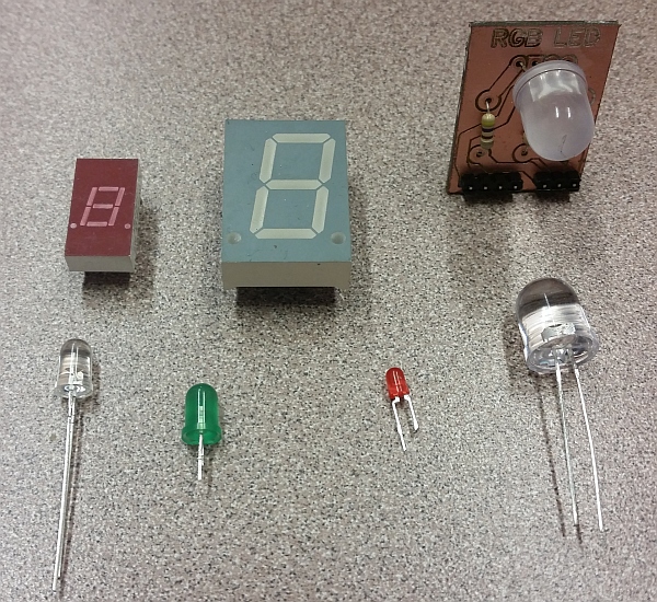
Just about every electronic device produced in the past twenty years or so uses one or more light-emitting diodes (LEDs). They are typically used as indicators (for power status, low-battery warnings, caps lock and number lock on keyboards, etc), but are also sometimes used to provide lighting (display backlights, “flash” lighting on digital cameras, as flashlights, etc.)
LEDs, in terms of light produced per watt consumed, are many times more efficient than incandescent light bulbs. They generate almost no heat, so nearly all of the power they consume goes directly into producing light. Because of this and other factors (for one thing, they’re extremely reliable when properly used), they have increasingly been used as replacements for incandescent light bulbs for indication and illumination.
If you look closely at modern traffic lights, you might notice that they are made up of a collection of dots, rather than a single glass lens. In place of a light bulb drawing hundreds of watts, a couple dozen LEDs do the same job while using far less power and requiring far less maintenance. Brake lights and tail lights on cars are also good candidates for LEDs, since reliability is important for those applications.
LEDs are also relatively inexpensive: a red or green indicator LED typically costs just a few cents when purchased in bulk. More exotic LEDs can cost a few dollars or more — with the price increasing greatly as the power increases (there’s still not a huge market for really high power LEDs, and they’re somewhat tricky to manufacture, so the economy of scale isn’t quite there yet.)
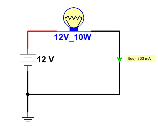
Using LEDs in a circuit is somewhat trickier than simply using a light bulb — although not much. A light bulb is basically just a low-value resistor whose resistive element gets hot enough to glow. They are, to some extent, self-regulating: a light bulb’s resistance increases as it gets hotter, limiting current flow through it somewhat. Given a light bulb of the proper voltage rating, it can simply be connected across the terminals of a battery or power supply.
LEDs, on the other hand, require a bit more finesse. First of all, they are diodes — which means that they only allow a significant amount of current to pass in one direction. The cathode of the diode (typically, the shorter lead on the LED package) must be connected to the negative side of the power source. Otherwise, no current will flow.
In addition, diodes (including LEDs) always have a characteristic “voltage drop.” A simple way of understanding this is that the diode will “try” to limit the difference in voltage across its terminals to no more than this “voltage drop.” It does this by lowering its effective resistance as the amount of current increases (see “Ohm’s Law”), so that the voltage drop remains nearly constant.
The problem is that too much current will burn out the diode. If an LED were connected across a pair of C-cell flashlight batteries (which produce roughly 3V in series), the voltage would be significantly more than the LED “wants” to see. It would lower its resistance until the voltage drop across the LED matched this built-in limit. By this time, the current flow would be so high that the LED would get very hot and quickly burn out with a brightly-colored flash. (If you’re lucky, you might even get to see the Magic Blue Smoke escaping. Once the Magic Blue Smoke is gone, the component is ruined.)
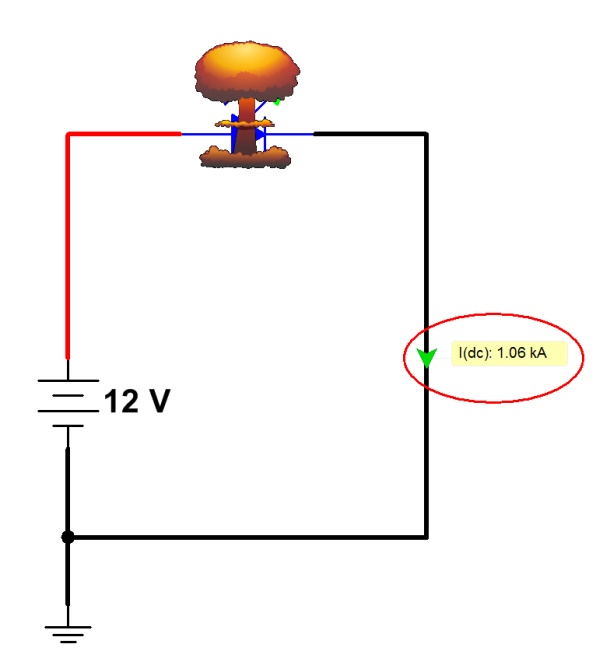
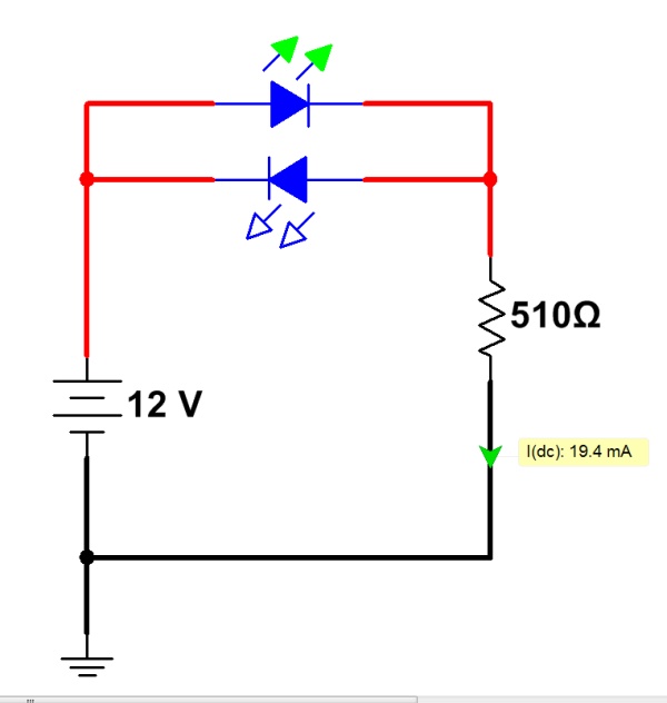
Without a current-limiting resistor, the LED will allow too much current to pass, and will be destroyed.
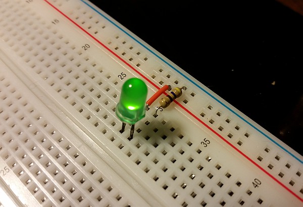
The solution to this is to put a resistor (typically 470 ohms) in series with the LED. This gives the rest of the voltage drop somewhere to go, and limits the current in the circuit to a value the LED can handle (typically 20mA or so, for a standard 5mm LED.) With the addition of a resistor (about 1 cent, in bulk) an LED can make a good, easy-to-use indicator for a circuit.
To calculate the correct size of the resistor, check the LED data sheet for the correct current that should flow through the LED. Then find the typical voltage-drop value from the datasheet (usually larger for blue and white LEDs; smaller for red LEDs). With these two values (voltage drop and current), you can calculate the correct series resistor as follows:
This calculation works by determining what the voltage drop should be across the resistor (that is, the total voltage minus the LED’s voltage drop per the datasheet.) This is divided by the current that should flow through the LED, to give the required resistance. (Remember Ohm’s Law?)
When connecting more than one LED (such as in a seven-segment numeric LED display), it’s best to provide a separate resistor for each LED. That way, the brightness of the LEDs remains constant regardless of how many LEDs are lit at one time. With all LEDs sharing a single current-limiting resistor, LED brightness will decrease if more than one is lit at a time.

