My new word for the day (okay, actually this week) is syntonization. I’d heard of synchronization, of course, but hadn’t heard of syntonization (setting two clocks or oscillators to the same frequency) until reading a usage guide for the Efratom LPro-101 Rubidium frequency standard units I’ve been working with.
Rubidium frequency standards work by tracking the natural frequency of an energy-level transition of Rubidium with a quartz PLL oscillator. This produces a very precise, accurate reference frequency — but one that can nonetheless be affected slightly by variations in the ambient magnetic field. For this reason, Rubidium standards typically are adjustable to some extent, and can be syntonized to other, similarly precise frequency standards.
Normally, syntonization of a Rubidium frequency standard is done in comparison with either a primary Cesium standard (too expensive for me, unfortunately) or with a precision GPS receiver (which appears a bit more affordable but which I don’t yet own.) Since the LPro units allow temporary adjustment via an input pin, though, it’s possible to syntonize one of them to another without having a primary standard available. This doesn’t guarantee absolute frequency accuracy, of course — but rather just taking Unit 1 at its word as to what the “real” value of 10MHz is, and tweaking Unit 3 to match that. For many experiments, it doesn’t really matter. Both are within a couple of parts per billion of the absolute frequency anyway, whether corrected or not.
The frequency adjustment pin on the LPro operates via a voltage-divider scheme: the pin can nominally be driven to any value between 0V and 5V, with higher voltage increasing the frequency by about 1PPB or so. This results in a rather coarse adjustment (relatively speaking), though. Instead of driving the pin directly, I decided to drive it via a 100k series resistor, effectively diluting the adjustment voltage. (The pin is internally held at 2.5V via a voltage divider with a nominal impedance of perhaps 100k ohms.)
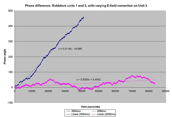
By watching the oscilloscope and phase measurement meter, I initially guessed that a drive voltage of about 2.084V seemed to cancel out the observed phase drift (the magenta line in the graph). I then let the oscillators run overnight. It nearly worked: whereas the units would drift in and out of phase every ten to eleven minutes with no correction, they now took about nine hours to do so. (This is the blue line in the graph below.)
After a bit more experimenting, I increased the drive voltage slightly to 2.090V. This, so far, has almost exactly cancelled out the phase drift. Although a few degrees of short-term phase jitter is present, along with perhaps 70 to 90 degrees of longer-term phase noise, the overall phase drift seems to be on the order of 1.8 degrees per hour. At this rate, it would take over a week for the two units to drift in and out of phase by one cycle. Running at 10MHz, it would take over two hundred thousand years for them to disagree by one second.

Phase difference in Units 1 and 3 (Unit 3 corrected with 2.090V via a 100k resistor). (Click for larger.)
0.005 degrees phase per second is 2000 seconds per degree.
Multiplying this by 360 degrees (I never really did like radians) gives 720,000 seconds per phase.
Multiplying this by 10,000,000 (since the units run at 10MHz) gives 7,200,000,000,000 seconds per one second of difference. This is one part in 7.2 trillion, or about 138 parts per quadrillion (PPQ). This is relative accuracy, of course, since I don’t have an absolute 10MHz reference standard that’s anywhere near this accurate.
…and to think, I used to consider 100PPM TTL oscillators to be precise…!


What type of resistors was used for this test?
Just a basic off-the-shelf 5% 100k, 1/8 watt resistor. All it does is dilute the voltage contribution from the offset input.
You should check into time-nuts and allan deviation.