One of the fundamental building blocks of electronics circuits is the voltage divider. By combining two impedances in series, a voltage can be obtained in between these two elements that is some (possibly complex) fraction of the original voltage.
For DC circuits, voltage dividers simply involve two or more resistances — and the math is straightforward: Vx = Vt * (Rx / Rt), where:
- Vx is the resulting voltage across one or more elements of the divider;
- Vt is the total supply voltage across the voltage divider;
- Rx is the impedance (for DC circuits, the resistance) between the output points; and
- Rt is the total impedance (for DC, resistance) of all elements of the divider.
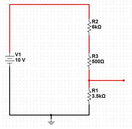
As an example, here is a schematic of a basic voltage divider set to produce 3.5V output from a 10V source:
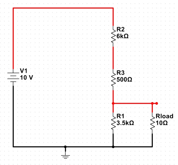
The above formula works well, if there is no significant load on the voltage divider. If the only thing connected to the output was a voltmeter, the output voltage would be very close to 3.5V. If, however, a significant load were attached (say, a light bulb with a 10-ohm resistance), the situation would be quite different…
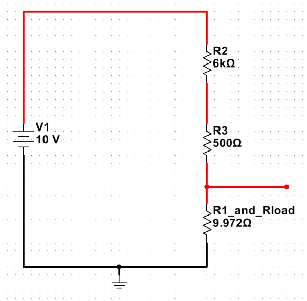
The voltage divider equation from above is still valid, but the new load resistor must be taken into account. With Rload in parallel with R1, the equivalent resistance of the two can be calculated with the parallel resistor formula: 1/Rt = (1/R1 + 1/Rload). The resulting resistance for the combination is about 9.972 ohms. (R1 hardly matters at all, at this point.)
Substituting this equivalent resistance in creates a very different-looking voltage divider…

The loaded voltage divider, with the R1/Rload combination replaced by its equivalent. (Click for larger.)
Calculating the new, loaded output voltage shows what a difference a low-resistance load makes: Vx = Vt * (Rx/Rt) = 10*(9.972/6509.972) = 0.01532V, or about 15mV.
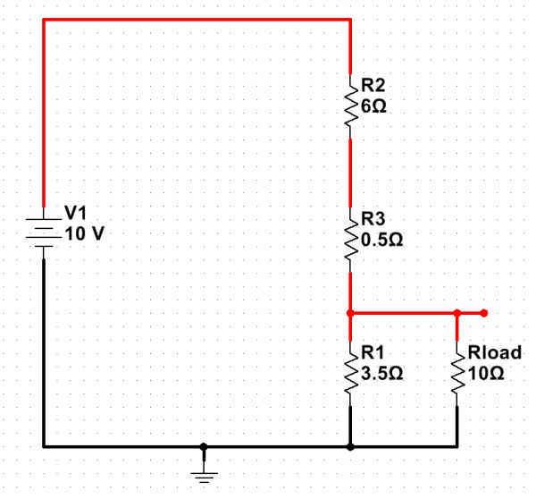
This dramatic voltage drop occurs because the load resistance is so small in comparison to the resistances used in the voltage divider. One possible solution for this is to use smaller value resistors in the divider, making things more equal:
This helps with the voltage-drop problem somewhat:
Vx = Vt * (Rx/Rt) = 10 * ( 2.593 / 9.093) = 2.85V
There’s a big price to pay for this, though! Even without the load resistor, there is now 1A of current through the voltage divider — at all times. At a supply voltage of 10V, this means that the voltage divider will be dissipating 10 watts even while not powering a load — not exactly energy-efficient. For this reason, voltage dividers are usually used to provide reference voltages for solid-state regulators, instead of being used to actually reduce the main power voltage directly.


