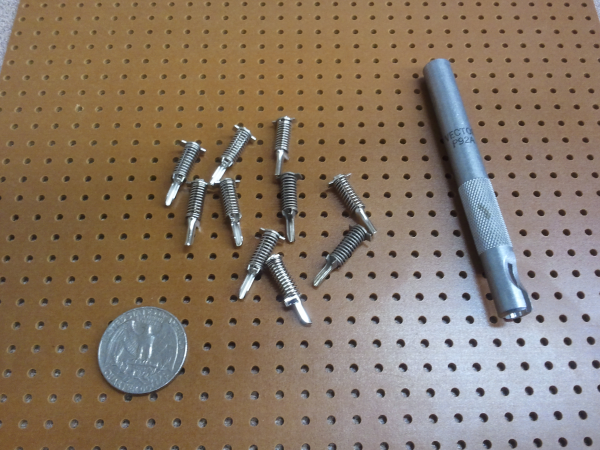
An older alternative to breadboarding is vector board. Prototyping with vector board involves inserting specialized “vector springs” into a board with pre-drilled holes. A pin insertion tool is used to insert the springs as well as to open them up to insert wires and/or component leads.
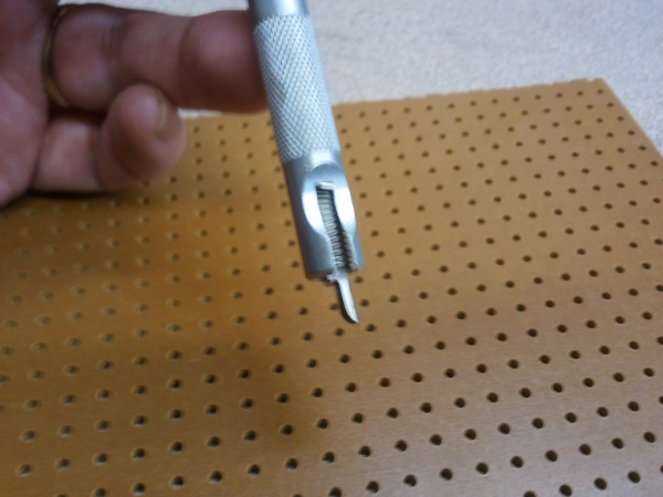
The first step is to use the tool to insert the pins. These are not easily turned once inserted, so it’s important to align them the way you want (or allow extra lead length).
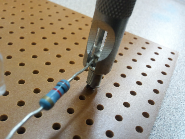
Once the pins are inserted, the tool is turned 90 degrees to press down on the spring and open the pin up so wires or leads can be inserted.

Using the insertion tool turned 90 degrees to compress the pin for component insertion. (Click for larger.)
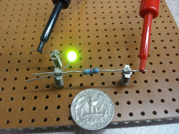
The rest of the circuit is constructed this way. It can be tricky to get both ends of a component seated using only one vector tool, since only one pin can be easily opened at a time. (A fingernail or screwdriver could be used, in a pinch.)
Overall, I can see why vector boarding isn’t popular these days — it’s quite a bit more time-consuming to build circuits this way, compared to using solderless breadboards. The circuits, once constructed, seem to be nearly as robust as if wire-wrap had been used, and a bit more reliable than breadboarded circuits.


