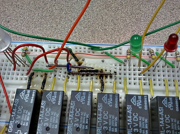
Note to self: Current handled by circuits on solderless breadboards should be limited to no more than 1A or so. Otherwise, things start to get smokier than normal, as demonstrated by what a prototype control board did to itself during a test run…
This kind of failure, though, demonstrates a valid diagnostic technique (albeit one taken to destructive extremes in this case): All else being equal, a conductor will become warmer when carrying more current. For example, it’s evident from the above picture what the high-current path was — through the first and fourth relays, which make up one half of an H-bridge setup. For some reason, the final part of the path — the short green wire at the upper left — didn’t get cooked, although it was carrying just as much current as the rest of the circuit. A different formulation of plastic, perhaps…?
Given an IR thermometer, this resistive heating effect (hopefully with less extreme temperatures) can be used to determine which chips are dissipating more power than others in a circuit. It can also sometimes be used to determine which device is causing a short — without risking burning your fingertips. Simple IR thermometers are available for around $20US; I picked one up a while back and keep finding new uses for it.


manual of main board says:
rms 3A
peak 8A
Eh, I was only over by 67% or so…