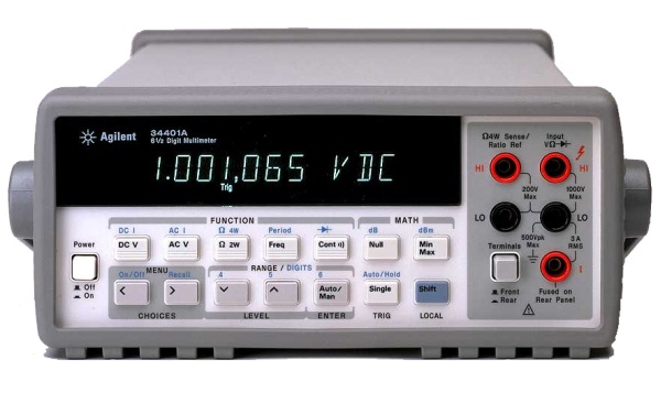
Digital Multimeters (DMMs) are quite versatile devices. Typically, they can be used to measure voltage, current, and resistance. Many DMMs are also capable of other measurements, such as continuity (an extension of the resistance function, actually) and frequency. Some are also capable of basic math operations on the measurements performed, including null offset and maximum/minimum readings. Here is a brief guide to using a DMM — specifically, an HP/Agilent 34401A. This type of meter is a “bench” meter — meaning that it is intended for use on an electronics workbench. It is somewhat portable, and includes a handle, but is significantly bulkier (and a bit more fragile) than handheld meters, so it is usually found on a workbench or in a lab. On the plus side, it is far more accurate than most handheld meters.
Measurement of voltage
The most basic function of a DMM is as a basic voltmeter. Most DMMs are autoranging, meaning that they automatically select the correct voltage range (millivolts, volts, etc) based on the measurement being made at the time. To measure DC voltage with the 34401A:
- Turn on the meter using the power switch on the left end of the front panel.
- Press the “DC V” button (if you will be measuring DC voltages.)
- Connect the negative probe (typically black in color) to the rightmost black “LO” port. (The two ports in the left column are used for four-wire resistance measurements, which are not covered in this guide.)
- Connect the positive probe (typically red) to the upper right “HI” port.
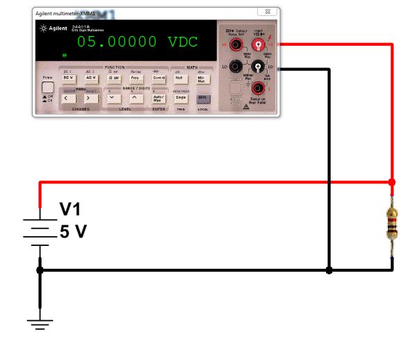
- Connect the probes to the circuit under test. Voltage is measured in parallel with a component, so you would not break the circuit to measure voltage.
- Read the voltage data on the meter.
Measurement of current
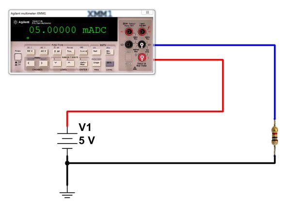
Another useful function of a DMM is as an ammeter — a meter designed to measure current flow. Since current flow is measured within a conductor, the meter must be actually inserted in the circuit in order to measure this flow. (There are “clamp” ammeters which do not work this way, but they are not covered here.) Because of this requirement, measuring current in a circuit is done differently than measuring voltage — the connections are made differently. Instead of simply clipping on to a circuit, the DMM replaces one of the wires in the circuit, and the current is made to flow through the meter. It is important to make sure that the meter replaces a wire of the circuit in this way, or else it could cause a short circuit. (That is, you need to break a connection, then insert the DMM in the gap.)
To measure DC current with the 34401A:
- Turn on the meter
- Press the blue SHIFT button once, then press the DC V button. This will put the meter into “DC I” (DC current) mode.
- Connect the negative lead to the right “LO” port
- Connect the positive lead to the right “I” port (at the lower right).
- Disconnect power to the circuit to be tested
- Choose a wire in your circuit where you will measure current. Disconnect it.
- Connect the black lead to one end of where the wire was (ideally, its more negative end.)
- Connect the red lead to the other end of where the wire was (ideally, its more positive end.)
- Reconnect power to the circuit to be tested.
- Read the current value on the meter’s display. (Note mA or A, as well.)
Measurement of resistance
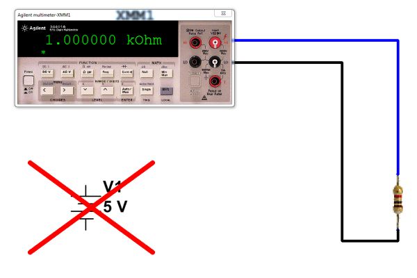
DMMs can also function as ohmmeters, allowing the measurement of resistance. Unlike measurements of voltage and current, this must be done with power disconnected from the circuit. (In fact, since parallel resistances can affect the measurement, resistance is usually measured with the component disconnected from the circuit, at least at one end.) When measuring resistance, the meter passes a small amount of current through the resistor and measures the resulting voltage. To measure resistance with the 34401A:
- Turn on the meter
- Press the “Ω 2W” button.
- Connect the negative lead to the right “LO” port
- Connect the positive probe (typically red) to the upper right “HI” port.
- Disconnect at least one end of the resistor to be tested from the circuit.
- Connect one probe to one lead of the resistor to be tested.
- Connect the other probe to the resistor’s other lead. (Direction doesn’t matter.)
- Read the resistance value on the meter’s display. (Note mΩ, Ω, kΩ, or MΩ.)

To measure resistance, disconnect the power supply and connect the DMM across the resistor to be measured. (Click for larger.)
The 34401A has many other measurement capabilities (frequency, continuity, four-wire resistance, diode check, etc.) It can even connect to a computer via RS232 or GPIB for automated measurements.


