Printing Large Numbers on Arduinos

2^32 (4,294,967,296) sounds like a big number. It’s over four billion, after all.

Large as it is, four billion (or more) is increasingly a perfectly reasonable number to be working with. For instance, it represents access to four gigabytes of memory, which isn’t much, these days. 32-bit math has become limiting, which is why computers switched to 64-bit hardware about ten years ago. (It was the memory addressing that made it happen.)

There’s good support for 64-bit numbers on desktop software, too. C provides the “unsigned long long int” (or uint64_t) type, which can hold numbers up to 2^64-1, and this covers nearly all of the cases that don’t fit in 32 bits.

Unfortunately, these large numbers, being newer than their 16-bit and 32-bit counterparts, aren’t always supported as well on smaller devices like microcontrollers. (After all, an 8-bit microcontroller has to do a lot of shuffling and carrying to do math with them.) Arduino C’s usual, super easy to use Serial.Print() function doesn’t understand how to handle anything larger than 32 bits. Trying an end run using tricks like sprintf(myString,”%llu”,bigValue) doesn’t work, either.

The proper solution would be to find a way to include 64-bit capable printf() code in the Arduino C compiler — but I suspect that if this were easy, someone would have done it by now. So I came up with a hack: use long division.

Integers, in any base, can be constructed digit by digit, and Arduinos can still do math with 64-bit numbers. So, to print out large numbers, take the number modulo ten, add that to the left end of your string, take it away from the original number, and divide it by ten. It’s not super efficient, needing an integer division operation for each digit — but it will still run in O(log(n)) time, and shouldn’t take very long at all, even for large numbers. It can be done in C readily enough, but the BASIC-like string concatenation capabilities of Arduino C make it easy.

Here’s the code, which should work for all Arduino-compatible devices:

void bigPrint(uint64_t n){
  //Print unsigned long long integers (uint_64t)
  //CC (BY-NC) 2020
  //M. Eric Carr / paleotechnologist.net
  unsigned char temp;
  String result=""; //Start with a blank string
  if(n==0){Serial.println(0);return;} //Catch the zero case
  while(n){
    temp = n % 10;
    result=String(temp)+result; //Add this digit to the left of the string
    n=(n-temp)/10;      
    }//while
  Serial.println(result);
  }

Now, 18,446,744,073,709,551,615 is the limit. Happy large-number computing!

Posted in Arduino, C, Coding, HOW-TO, Math | Tagged , , , , , , , , , | Leave a comment

DIY scroll wheel

For almost thirty years, I’ve preferred trackballs to traditional mice. Flipping the mouse geometry upside-down means that you can give the trackball a spin to move the cursor quickly, without having to bother with picking up the mouse and moving it back onto the mousepad over and over. Also, more importantly, trackballs don’t need to move around like a traditional mouse does, and so take up a lot less desktop real estate. It’s like having a mouse with an infinitely large mousepad and an infinitely long arm. I honestly don’t know why traditional mice are still a thing.

A Logitech Trackman Marble(tm).
Image shamelessly snagged from Logitech’s site. (Go buy one. They’re good.)

The one drawback to trackballs, however, is that they generally don’t come with scroll wheel functionality of any kind. And while the scroll wheel is still not up there with the left and right mouse buttons in terms of importance on a PC, there are still far too many apps that require it, and a lot more than can make good use of it. The map in Skyrim, for example, can be zoomed to some extent — but only with a scroll wheel. Zooming the view in and out in X-Plane, while possible using the keyboard, is much faster and more intuitive using a wheel input. Also, all of the many knob-based inputs in a typical simulator cockpit can be used with a scroll wheel if the mouse cursor is on them. This is a lot more realistic than trying to click on the correct edge of the image of a multi-function knob on your screen.

Scroll wheel functionality would be useful — but the hassle of moving back to a traditional mouse just isn’t worth it. (I brought in my own Logitech Marble Mouse to work so I wouldn’t have to use a traditional mouse.)

Boards like the Arduino Leonardo now make this a very easy problem to solve! The Leonardo can implement a “HID” (Human Interface Device) via USB, and can appear as a USB keyboard and/or USB mouse to a host computer. Since it’s pretty straightforward to get an Arduino to read a quadrature encoder (see code below), a few lines of code are all that’s needed to get it emulating a scroll wheel.

Here’s the encoder I used — any similar quadrature (relative position / “jog dial”) encoder should work.

Hookup is almost as simple as it gets: 5V to 5V, Ground to Ground, then pick GPIO pins to use for switch (the pushbutton), data, and clock. (Really, phase A and phase B.) I used pins 2, 7, and 8 (more or less arbitrarily), but as long as your pin choices match the ones you set in the code below, it should work.

Here’s the code (designed for an Arduino Leonardo).

//Simple scroll wheel implementation for Arduino Leonardo and similar
//Uses quadrature encoder and USB HID library
//CC-BY-NC 2020, M. Eric Carr / eric at paleotechnologist dot net

#include<Mouse.h>

const int SWITCHPIN = 2; //Push switch function of encoder (for future use)
const int DATAPIN = 7;   //Phase A of encoder
const int CLOCKPIN = 8;  //Phase B of encoder

void setup() {
  pinMode(SWITCHPIN, INPUT); //For future use
  pinMode(DATAPIN, INPUT);
  pinMode(CLOCKPIN, INPUT);
  }

void loop() {
  //Quick-and-dirty quadrature tracking. Counts when A high and B changed;
  //this should produce one count per set of four quadratures.
  //TODO: Give this a little hysteresis by not incrementing and decrementing
  //the count at the same place in the cycle.

  //DO NOT PUT SIGNIFICANT DELAYS IN THIS LOOP; it relies on running fast enough
  //to not miss any transitions. 1ms delay may be too much. 10ms can cause problems.
  //There are four transitions per "click" of the dial; if you spin it quickly,
  //you could go through several dozen transitions in a fraction of a second, causing
  //the count to be in error if this loop is too slow.

  static int oldA=0,oldB=0;
  int a,b;

  a=digitalRead(DATAPIN);
  b=digitalRead(CLOCKPIN);

  if(oldA!=a || oldB!=b){

    if(a==HIGH){
      if(b==LOW && oldB==HIGH){Mouse.move(0,0,1);}  //Scroll up
      if(b==HIGH && oldB==LOW){Mouse.move(0,0,-1);} //Scroll down
      }

    oldA=a;
    oldB=b;

    }//if

  }//loop()

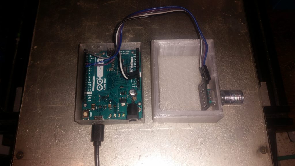
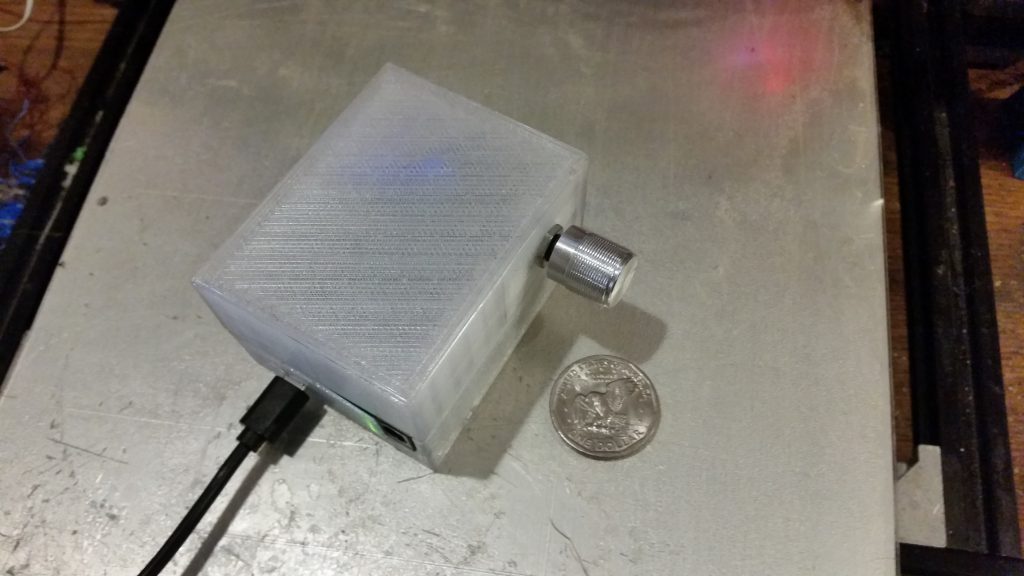
Once everything was wired and tested, I modified a Leonardo case I found on Thingiverse to expand the lid, allowing space for the encoder. It’s even somewhat ergonomic, considering it’s a prototype…

The Leonardo is more-or-less Uno sized,
but with a microUSB cable instead of Type B.
The completed scroll wheel prototype. It doesn’t look like much, but it’s certainly useful.

Happy scrolling!

Posted in Arduino, C, Coding, Digital, HOW-TO, User Interface Design | Tagged , , , , , , , , , , , , | Leave a comment

Pixel Art

Fill a blank screen with a band of randomly-colored pixels horizontally across the middle fourth or so. Then, create a loop where you select a pixel at random and decide whether it matches the pixels to its north, south, east, or west more closely. Swap it with its nearest neighbor in the new neighborhood it matches best (disregarding what the other pixel might think.)

Repeat this a few billion times or so, depending on resolution, and you get something like this (click each image to see it full-size):

“Crystal Conduit”
(All images CC:BY/NC/SA M. Eric Carr / Paleotechnologist.Net )

Seed the screen with two such bands of random pixels close enough together, and they may fuse:

“Crystal Crossovers”
(CC:BY/NC/SA M. Eric Carr / Paleotechnologist.Net)

Filling the whole screen with random pixels (at a higher resolution), while adding in 40% black pixels (RGB zero) gives the following, after letting it run for a few days:

“Crystal Labyrinth, Annealed”
(CC:BY/NC/SA M. Eric Carr / Paleotechnologist.Net)

These were more or less what I expected, if a bit more organic and natural-looking. After all, the process isn’t perfect; the pixel that is selected is moved to where it will fit best, without regard to whether that makes the pixel it swapped places with fit better or worse.

Seeding a blank screen with many narrow bands produced something strange: bulbous rainbow shapes oddly melted onto fragmenting lines. Some of them seemed to resemble hummingbirds or maybe Kiwi birds, if you look at them right.

“Crystal Lines”
(CC:BY/NC/SA M. Eric Carr / Paleotechnologist.Net)

If you play with the spacings and runtime, you can get weird shapes that almost look like some kind of alien biology:

“Alien DNA”
(CC:BY/NC/SA M. Eric Carr / Paleotechnologist.Net)

I then wondered what would happen if I intentionally broke the process in a subtle way. Now, when each selected pixel looks at the neighborhoods immediately north, south, east, and west, it gets confused about west and south 90% of the time: If west looked like a better fit, it swaps to the south. If south looks better, it swaps west. (The other 10% of the time, it chooses as usual.)

What would happen? I had no idea. I got this:

“River of Light”
(CC:BY/NC/SA M. Eric Carr / Paleotechnologist.Net)

It’s amazing how simple rules, repeated a zillion times, can create something beautiful — or at least interesting. Not only did I not intend to create that particular image, I only had a vague idea of what it would do. This is art, for sure — but it feels more like cross-pollinating plants to come up with a more beautiful flower.

I didn’t even choose the colors, other than occasionally mixing in a percentage of completely black pixels to help give it some contrast. The rest were chosen randomly (uniform distribution*) from the 2^24 possible colors.

Even more interesting, the image will evolve over time. I plan to make a video of it eventually, but here’s what it evolved into roughly a week of runtime later:

“Void Island”
(CC:BY/NC/SA M. Eric Carr / Paleotechnologist.Net)

It should be interesting to find out what images result with slightly more complicated algorithms than simplistic best-fit-finding.


* Regarding random numbers: For another project, I’m testing random number generators from various machines and languages. I started with the FBC compiler used by FreeBasic; it did quite well on the Dieharder series of randomness tests. More about that in a later post, hopefully.

Posted in BASIC, Coding | Tagged , , | Leave a comment

Indistinguishable From Off

When diagnosing a problem, remember to check the basics.

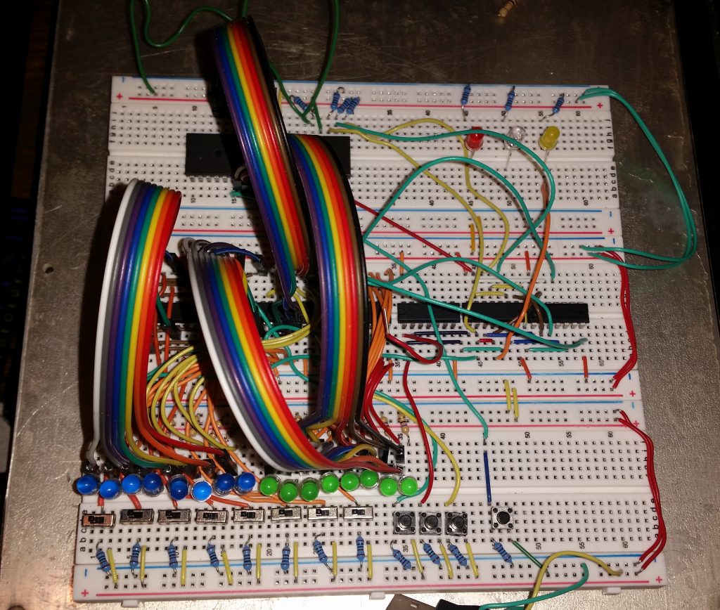
I was working with the prototype of the latest (take-home breadboardable) version of the DrACo/Z80 computer, making sure it still worked, when it seemed to develop a problem right at the end of programming before I was going to switch it to Run mode.

The latest iteration of the DrACo/Z80 computer, hastily redesigned
to be as breadboardable as possible on a couple weeks’ notice.

I had gone through and cleared out the first few memory addresses, since in this configuration, it’s easier to load a single number into the data latch and then program those locations all at once so you don’t have to reload the data. So addresses 00, 01, and 02 were all set containing 0x00.

I then switched back to address 00, moved the switches to 11000011 to represent the C3 (jump) opcode, and hit Latch Data to latch it in to memory. Nothing happened, which was as expected. I then hit Write to load it into memory, and the display stayed blank. That was not according to plan.

I pulled the schematic out and got about two or three logic gates into debugging it when I noticed that all the logic was at zero. After a brief search, I found a plausible explanation.

If all the logic signals are low, that’s usually a power problem — and it seemed to be, in this case. We may be building a 40-year-old computer, but the chips we’re using are modern CMOS variants — faster, cheaper, and often much more power-efficient. These are not the power-hungry 7400 series TTL chips of yesteryear. They do the same thing, but draw far less current.

In short, a good chunk of the power budget for this computer goes to run the twenty or so LEDs. The chips themselves draw very little current, in comparison. Maybe a few tens of milliamps or so, compared to 10-20mA per LED, depending on a bunch of things.

When switching back to address 00 which had data of 0x00 in it, all of the LEDs were out at the same time while I fiddled with the switches to enter the C3 opcode. This left the whole circuit drawing next to no power for maybe five or ten seconds (and little power for the previous short while, too.) The USB battery running the show had apparently sensed what it thought was no appreciable load, decided that nothing else was connected that needed charging, and gone to sleep, cutting off power to the whole computer.

Or, maybe it hadn’t…?

After powering it back up, re-entering (all three bytes of) the test program, and setting it back to address zero with all LEDs off, the battery isn’t powering off. Maybe the power wire jiggled the other time — but it was connected when I looked, and an interruption in power usually means the memory contents are randomized. It’s noticeable.

Well, we are kind of pushing how complex breadboard projects should get before switching to circuit boards. Sometimes they’re a little wonky.

Note to self: Include a power LED in the next version just in case — as well as an explanation that it may actually be essential if running from a battery.

Posted in Digital, DrACo/Z80, Drexel, Electronics, Fundamentals, Power, Troubleshooting | Leave a comment