The USB-C High Voltage Hydra: Don’t Get Bit!

Multi-connector USB-C charging cables, which allow you to charge multiple devices simultaneously using a single USB-A port, are certainly convenient. These cables typically feature one data-capable connector and multiple charging-only connectors, making them seemingly ideal for powering multiple devices on the go. However, as with many technological conveniences, there are hidden risks.

Recently, I purchased a 1-to-4 USB-A to USB-C charging cable. This cable includes one data cable and three charging cables. Initially, it seemed like a great way to simplify my charging setup. However, I soon discovered a significant design flaw: the voltage on the V+ line follows the voltage requested by the device on the data cable.

The monster. Whatever voltage the data connector (weirdly in orange) requests, everybody gets(!!)

USB defaults to +5VDC power, which has been the standard since USB first came out. (How much current a device should draw is another discussion.) But with the USB-C Power Delivery (PD) specification, USB-C capable devices can request higher voltages and/or current limits, which will then cause the power supply to change to that higher voltage.

For example, when I connected my Samsung A71 phone to a power bank via this cable’s data connector, it requested and received 9V on the power rail (as measured by a handy passthrough USB analyzer.) This 9V was then applied across the V+ lines on the other three cables, potentially subjecting any devices connected to the charging-only connectors to a voltage they were not designed to handle. (Needless to say, I suspect this cable is not standards-compliant. Hey, it was cheap.)

USB-C Power Delivery (PD) is a specification that allows devices to negotiate the power they receive. This negotiation can result in voltages of 5V, 9V, 15V, or even 20V, depending on the device’s requirements and the charger’s capabilities. While PD provides a great way to supply more power when needed, it also introduces risks when multiple devices are connected without proper isolation.

Not all USB-C devices are tolerant of higher voltages. Many devices that do not support PD negotiation are only rated for 5V. If these devices are exposed to higher voltages, they can be damaged or even rendered inoperable. This makes it crucial to ensure that devices on the charging-only connectors are either capable of handling the higher voltage or are protected from it.

If you’re charging four of the same type of thing (like those USB-rechargeable AA batteries), such cables will probably generally work (as long as the individual devices don’t draw too much power without negotiating for it.) But if you just plug in devices to charge them (as many purchasers of these cables will no doubt do), take care that the data-cable device doesn’t see a native USB-C connection, request 20V to fast-charge itself, and fry the rest of the devices connected to the cable.

After all, power is proportional to V2, so a device drawing 1x power at 5V will draw 16x the power at 20V, assuming it is essentially a resistive load. This will usually end with some part of the device releasing its magic smoke due to trying to dissipate 16x as much power as it should.

So, while there are good uses for such cables — use them carefully!

Coauthored with GPT-4o.
(They wrote the article from a description I provided; I edited for style.)

Posted in Design, Digital Citizenship, Electronics, Power | Tagged , , , , | Leave a comment

Artisinal Digital Audio

The I2S protocol is pretty straightforward — it uses a bit clock and a word clock to transfer raw (stereo or mono) audio data in digital form. The clock speeds determine the sample rate, and the number of bits sent per word clock determines the sample depth. In theory, it’s possible to mathematically define the waveform of the audio you want to create — sample by sample and bit by bit.

And that’s the upside and the curse. You get perfect control over the audio you produce (in digital form, anyway) — but in return, you have to feed the beast. If you’re using CD audio parameters, that’s two, 16-bit audio samples that need to be generated, 44100 times every second.

Quick, what’s 32,000 * sin(440*curSample/SAMPLES_PER_SECOND)?
Too late — you only had about 11.33 microseconds!

This sort of thing is why, when I asked GPT-4o for example I2S code to generate a 440Hz test signal, it used the sinf() function, instead of the usual sin(). I’m still not 100% sure which helpfully-included-for-me-because-Arduino library is being used here, but running benchmarks, it’s something like 6x faster, for a slight loss in accuracy. I think it’s using 6-term Taylor series expansions, if it’s similar to sinf() code I found online.

Could sine computation be made even faster, if some memory were set aside as a lookup table? I coded up a fastSine() function to look up float32 sine values from a table, based on an integer scaling of a float32 parameter. Swapping this in for sinf() and testing it by having each function do a million-sin summation, it worked — and was some 20% faster! At about 1.25 microseconds each, I can afford to crank the sample rate up to an almost reasonable value!

Making sine table...
Done.
Testing sin()...(3791.946274): 92282.847 ops/s (10836.250 ns/op)
Testing sinf()...(3791.948715): 657273.786 ops/s (1521.436 ns/op)
Testing fastSin()...(3787.528053): 807325.347 ops/s (1238.658 ns/op)

Well, it almost worked. After a while, the waveforms started to look somewhat shaky — and this got worse as time progressed. Resetting the ESP32 cleaned things back up, so something was going wrong with the software. Was all this caused by that ~1% error?!?

Sines with float32 precision error

Thinking I had introduced an error with the fastSine() function, I recompiled with the left channel using sinf() and the right channel using fastSine(), to see when they started to differ. Weirdly, both of them acted similarly — so whatever the problem was, it wasn’t the fastSine() code.

After some diagnosis, the problem turned out to be caused by floating point dilution of precision. Floating point numbers are represented in a mantissa-and-exponent format. Oversimplifying, they’re scientific notation numbers in binary — and there is a limited amount of precision available for the mantissa. Larger numbers can be represented, but at the cost of precision. Double the size of the number, and you halve the precision. Once numbers get larger than 2^24 or so, the representation inaccuracy in float32 can be larger than 1.0. And for angles, we need to do better than this.

Capping the sample number at I2S_SAMPLE_RATE*24 seemed to be a good compromise, and the waveforms seem to have noticeably fewer glitches, now.

Moral: float32s have about 23 bits of precision. Choose your scale carefully!

Posted in Arduino, C, Digital, I2S, Math, Troubleshooting | Tagged , , , , , , | Leave a comment

MobiFlight

Flight Simulation is a fun hobby, and has evolved from interesting-but-not-especially-realistic vector graphic depictions of flying something that vaguely resembled a Cessna 182RG around the Chicagoland area, to impressive, raytraced simulations of just about every type of aircraft out there, often with highly accurate physical simulations backing up the aircraft performance.

MS Flight Simulator 1.0, about to overfly KCGX Meigs,
in what we are assured is a Cessna 182RG. (Image: Wikipedia)
On final approach to the virtually-restored Meigs, in an SR-22 in FS2020.

Of course, realism takes a hit when you’re interacting with these glorious models through a computer screen — and manipulating controls by clicking on them and dragging them with a mouse. If real aircrews had to do this to control their planes, they could make it work — but they would declare an emergency due to how difficult (and therefore risky) it makes things. It would be nice to have the same kind of controls for simulation that the actual aircraft use, but this has generally been a hassle, having to program each control to interact with an API such as SimConnect.

MobiFlight (freeware) makes connecting hardware inputs and outputs much simpler. Connect your controls to I/O pins on supported Arduino models, upload the MobiFlight firmware to the board, download and launch the connector software on the PC, and you’re up and running. Make a change on the physical controls, and it will be reflected in the sim.

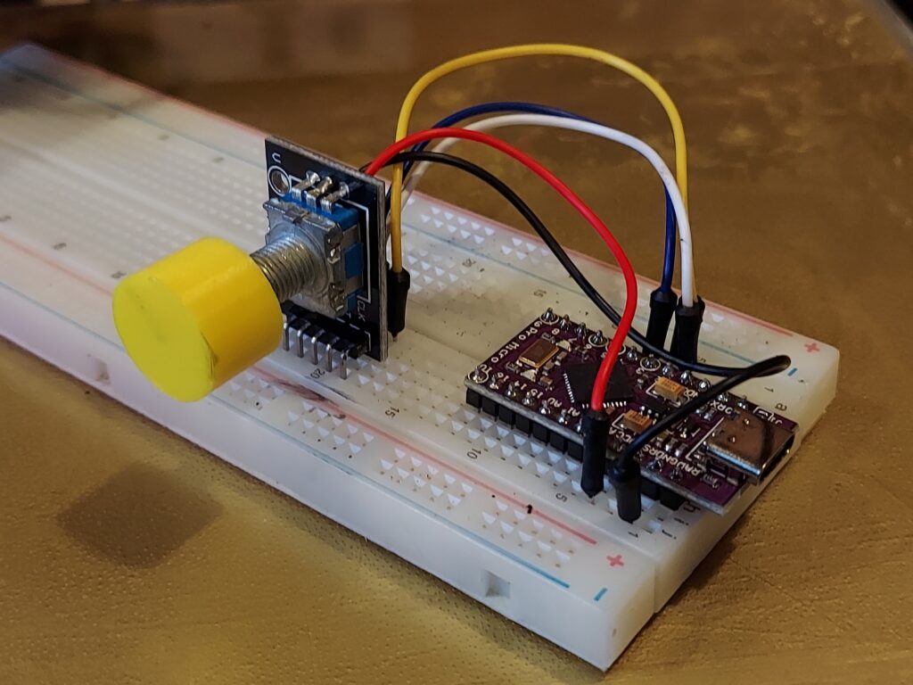
A quadrature encoder plus SPST switch, used to set the heading bug.
This, plus plugging in the board via USB, is all the hardware setup needed!

As a first test, I implemented a heading bug selector, and verified that it works in the Cessna 172, Cirrus Vision Jet, and the PMDG 737-700. From here, I’m planning to start to recreate the 737 controls, panel by panel. The eventual goal is to have at least the main control panel in the correct position, so I can look over in VR and find each control where it should be, without having to see the physical device.

Posted in Arduino, Aviation, Flight Simulator, User Interface Design | Tagged , , | Leave a comment

Z80 End-Of-Life

I guess it had to happen sometime — and close to fifty years is one hell of a good run for an 8-bit microprocessor from 1975. This week, Zilog announced that it would be moving the storied Z80 microprocessor family to EOL status, and called for last-time-buy orders through June 24.

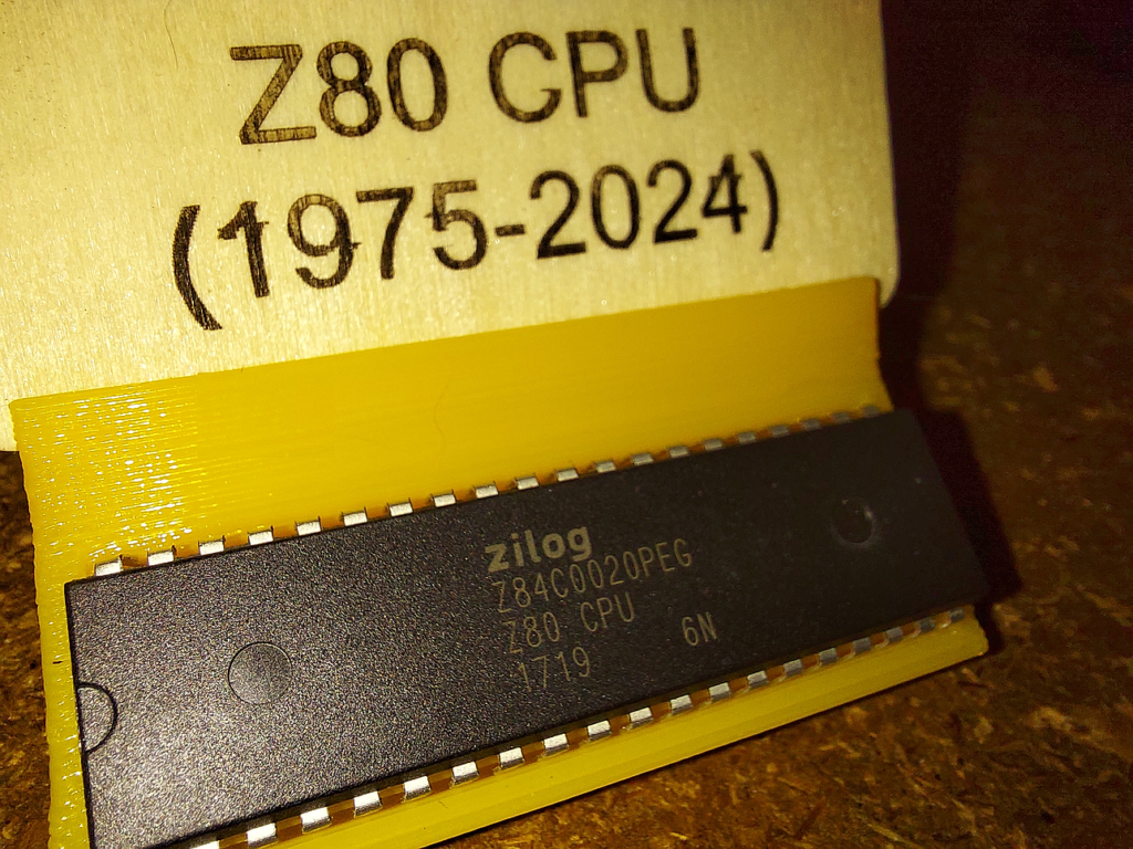
I took the opportunity to place a small symbolic order for a single chip for the Mini Museum — a processor that 1975 would have drooled over. The Z84C0020PEG is a power-efficient, DC-clockable, 20MHz CMOS version of the venerable Z80 microprocessor. In car terms, it’s a Z80 with a quad barrel carb, dual chrome exhaust, and a sweet paint job.

A 20MHz CMOS, DC-clockable Z80.
Even this one is five years old, bought “new” from Mouser this month.

The Z80, itself a software-compatible improvement on Intel’s popular 8080 microprocessor, is probably in several billion devices, at this point. It has been used to control everything from robots to the Nintendo Game Boy to microwave ovens, as well as its usual use in 8-bit computers, typically running the CP/M operating system. It anticipated the past few decades of PC upgradability by providing a faster, more capable version of the 8080 that could run on the same software as the 8080, if needed, just like later generations of PCs can (usually) run software from at least the previous generation or two.

While the eZ80 will continue to be produced for the foreseeable future, it’s not quite the same for hobbyists and educators like me who grew up with the Z80 (it powered the Timex-Sinclair 1000, which was my first computer). I understand the business case for the decision, though — we’ve long since switched to 32-bit processors even for our Microcontrollers class, and last year, we replaced the Z80 Microprocessors course content with a Verilog-based approach, where students design their own processors. (I do still use the Z80 for opcode examples.)

Although I wouldn’t use a Z80 in a new design, it’s still bittersweet to see it replaced by more modern tech. But I guess for nostalgia, we’ll always have the good old 16F84A. (That’s so deeply entrenched in engineering curricula that Microchip will be stuck making it until the heat death of the Universe!)

Posted in Components, Current Events, EET325, Electronics, Lore, Nostalgia | Tagged , , , , , , , | Leave a comment