Kung Fu Science

Well, more like quick back-of-the-envelope-calculation science. Sometimes, it’s useful to be able to quickly determine if an interesting new idea is plausible or not. Many times, guesses about the available data have to be made, but a quick estimate of the plausibility of an idea is often still possible.

I heard on Citizen Scientists’ League that NASA was “taking high-resolution photographs of the Moon” in order to prove to skeptics that the astronauts had indeed landed there and walked around. This is a noble goal — and the moon is right in our backyard, astronomically speaking — but viewing details that small still must require incredible telescope resolution. Would such a thing be possible? How could we tell if this is easily done, tricky but doable, possible but very difficult, or impossible?

A quick Wikipedia search of the usual suspects turned up the fact that the Hubble actually doesn’t have very good angular resolution, compared to many (much larger) major ground-based telescopes. (That’s because it’s relatively small — about the size of a bus — and so doesn’t have the huge aperture needed for very high resolution.)  So, I decided to use the specifications of the optical interferometer at Paranal as a quick test case. Here is an example of how a few minutes’ thought can give an idea of how plausible an idea is…

Could we photograph footprints that the astronauts left on the Moon, from the Earth?

The interferometer at Paranal is said to have “milli-arc-second” resolution

The size of the resolvable object for a telescope depends on its distance.
So, how far away is the moon?

  • 384,399km semi-major axis
  • ~1738km moon radius
  • ~6378km earth radius
  • = ~376,283km distance (once the radii are subtracted)

(source: Wikipedia entries on the Moon and the Earth)

Basic trigonometry tells us that tan(angle) = opposite / adjacent.
So, tan(resolution angle) = min_feature_size(m) / distance(m).

tan(1 milli-arcsecond)=min_feature_size(m) / 376,283,000m
min_feature_size(m) = tan(1 milli-arcsecond) * 376,283,000

1 milli-arc-second = 0.001 / 3600 degree = 2.7778 x 10^(-7)
tan(2.7778 x 10^(-7)) ~= 4.848 x 10^(-9)

4.848 x 10^(-9) * 376,283,000m = 1.82427m. (A fairly typical adult human height, for example.)

So, we could probably see the landers, but probably not footprints.

..and that’s if using optical interferometry is possible.
According to the Dawes limit (from Wikipedia; I’m no optics expert),
an 8.2m telescope would itself have a resolving power of about 25.8m on the Moon.

(These calculations also don’t take into account telescope stability, tracking precision, etc. As anyone who has used a telescope knows, the Earth’s rotation makes celestial objects appear to move across the sky when seen from a fixed vantage point on Earth. The fact that the Moon is also orbiting the Earth doesn’t help, either.)

Calculations such as this are fun, and provide a good, intuitive understanding of scientific principles. It’s kind of like Mythbusters on a scrap piece of paper — but unfortunately without any cool explosions. Maybe someday…

Posted in Digital Citizenship, HOW-TO, Math, Science | Leave a comment

C Minus Minus

Note to self: When writing programs in C that need to read ports on PIC microcontrollers, copy the port data to a local variable without trying anything fancy.

In normal, standard C, a trick like the following should work nicely…

if (PORTC & 0x08 == 0x08){ foo();}

In Hi-Tech C, however, you don’t actually seem to get the current value of PORTC by doing something like that. I’m not sure *what* you get, but it certainly isn’t the current input value. Instead, you need to use the C equivalent of speaking slowly and using small, simple words:

temp = PORTC;
temp = temp & 0x08;
if (temp == 0x08){foo();}

This is annoying, but wouldn’t be an undue burden if properly documented. What *is* annoying is having to waste half a day tracking down why the code wasn’t working correctly!

Posted in C, Coding, Digital, HOW-TO, PIC Microcontrollers | Leave a comment

(Towards) A 555-Based Computer

It’s well known that the 555 timer IC is a very versatile piece of technology. (The fact that it’s still being produced after nearly forty years attests to this.)

…but can it compute?

As it turns out, the native “A * ~B” gate (see “Boolean Logic with 555s“) can be made into a S/R latch, with the addition of a few resistors and a diode. (The 555 actually does contain such a latch inside it, but not all of the latch ports are exposed as pins.) The diode is needed to block a low (inactive) signal from the Set pin from resetting the circuit when it is in the on state. The reset resistor (connected to DIS/CON, not RST) may not be needed; this design was hastily done in time for the 555 contest and I went with the first implementation that worked.


A transparent S/R latch using a single 555, a diode, and two resistors. (Click for larger view)

This S/R latch circuit allows a 555 to function as one bit of static RAM. With enough 555s — and no other active components —  a primitive (but Turing-complete!) computer can therefore be built, using only 555s! (For this implementation, I’m using diodes, which are technically active, but even these are not essential. Given enough 555s; S/R latches can be built from logic gates alone, which can be built from 555s, as demonstrated in another post. The diodes do help reduce the circuit size quite a bit, though.)

One tricky factor is the lack of tristate output functionality; the 555’s output is always high or low, never tristated. This can be mitigated by using OR gates (a NOR cascade with a final inverter, as shown below) to combine the various possible sources onto a single bus. As long as only one source is active at a time, its data will be carried through correctly — and no electrical contention (shorted outputs) is ever possible, even if more than one source does go active/high at one time. Multiplexing N outputs into a single line via OR logic therefore requires N+1 555s. (This could also probably be done with diodes and a pulldown resistor, but the eventual goal is an all-555 design.)


Building an OR multiplexer, to get around the tristate problem (click for larger view)

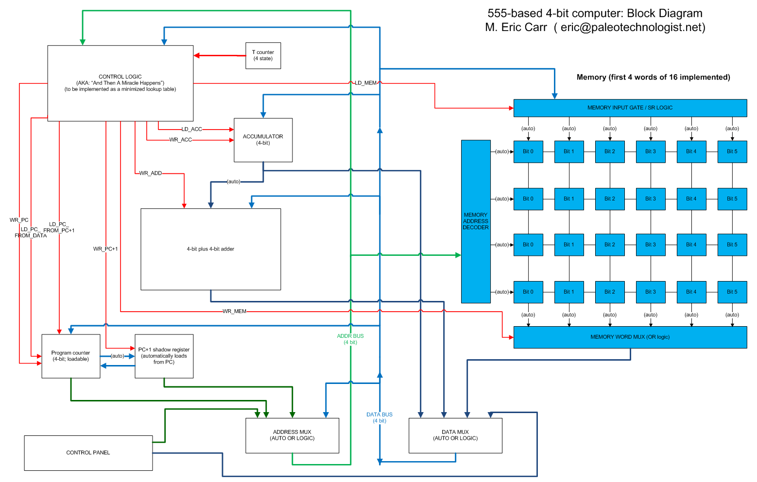
Since using 555s as logic gates is extremely inefficient in terms of space and wiring complexity, the computer design is necessarily quite simple. A six-bit word size allows for orthogonal instructions: 2-bit opcodes with 4-bit operands. This will allow for four possible operations, and 4-bit operands ranging from 0 to 15. Twenty-six or so 555s are needed for each word of memory, plus extras to combine them onto the output lines, so I have built just four six-bit words for the time being, rather than completing all sixteen possible memory locations. Another six-bit word for the accumulator has been completed, along with a four-bit word for the program counter. The 2-to-4 address decoder for the memory is complete (visible on the breadboard at the side). The rest of the control and processing logic is planned but not built at this point. Here’s the planned block diagram:


Block diagram; the memory, decoder, and multiplexer are complete. (Click for larger view)

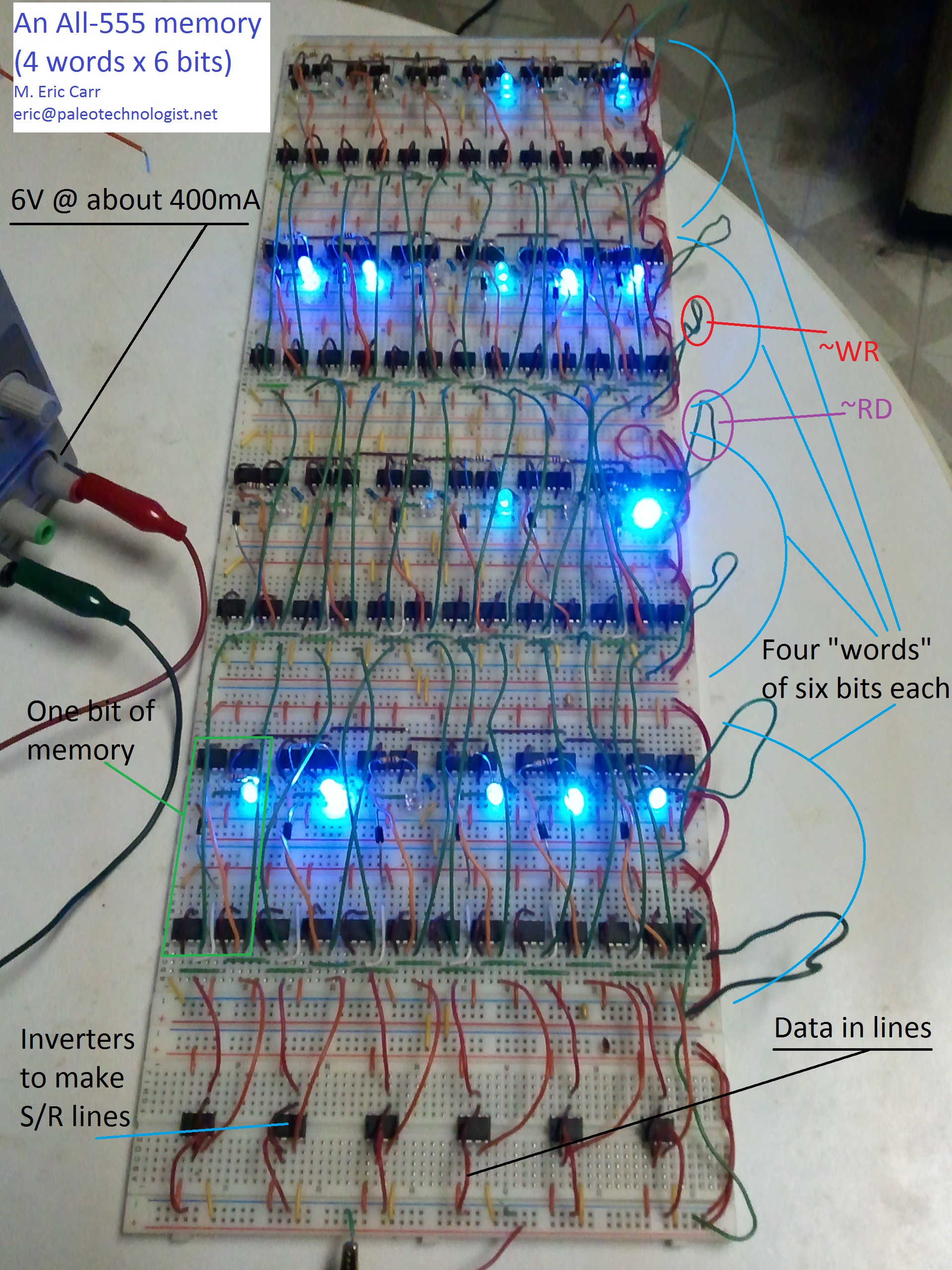
Here’s a picture of the memory subsystem:


The 555 memory subsystem (4 words of 6 bits). All chips are 555s. (Click for larger view)

Here is a video of the memory in action (storing several words of data). The LEDs show the state of the memory; with the addition of a (mostly complete) NOR cascade multiplexer, the memory will be capable of outputting its data onto a single data bus. With the addition of a (completed but buggy) address demultiplexer, the memory subsystem will be ready to take its place in the 555 computer.

Unfortunately, lack of time (I get to do a lot of interesting things at my day job, but they do seem to insist that I show up for work) has prevented me from completing the entire design in time for the contest — but the design is feasible. Hopefully, I’ll be able to have the whole thing up and working sometime this summer. If so, I’ll post the details here.

Posted in 555, Digital, Electronics, Nostalgia | 8 Comments

Overclock that puppy!

“If it ain’t broke — TWEAK IT!”
— Some anonymous geek

With my 555-based computer (or at least memory) entry, I figured I had a pretty decent shot at doing well in the “complex” category of the 555 contest — but I was having trouble thinking of a suitable entry for the “minimalist” category. It seemed that most of the interesting minimal uses had probably been thought of long ago by folks far better versed in analog design than I was.
At the same time, I happened to be reading an article (on Tom’s Hardware, I think) about PC performance tuning. I looked at the can of compressed air on my desk, mentally turned it upside down — and I had my idea. Let’s see how fast this thing will go, given insane cooling and, if need be, a healthy dose of voltage! (The 555 is specified to run on up to 18V, so there should be a lot of room there.)

With a reasonably-well-stocked (but not professional) home lab, as well as the time constraints of the 555 contest, I was limited to breadboarding the testbench, rather than building a nice, stable circuit board for proper overclock testing.  (Besides, this isn’t my main entry in the contest — just a fun little side project. The main one is a fun, bigger project!)

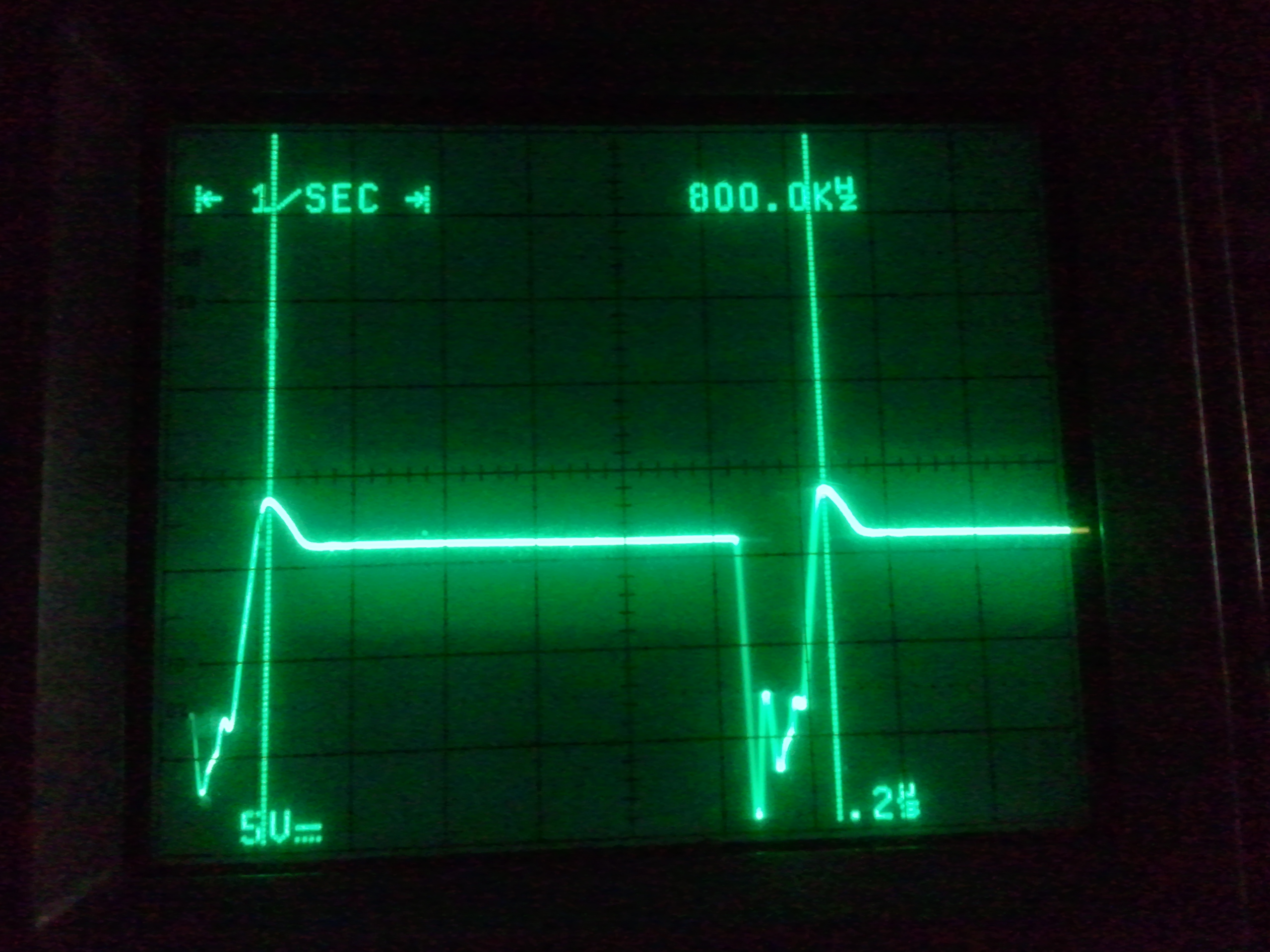
The first step was to go for a fast, but not *too* unreasonable, overclock. First stop: 800 kHz. This is already 8 times the highest “official” frequency shown at the top of the frequency-vs-RS-values chart in Figure 14 of the NE555 datasheet. This was fairly easily obtained, although the waveform was less than clean.


800kHz -- an 8x overclock, to start things off!

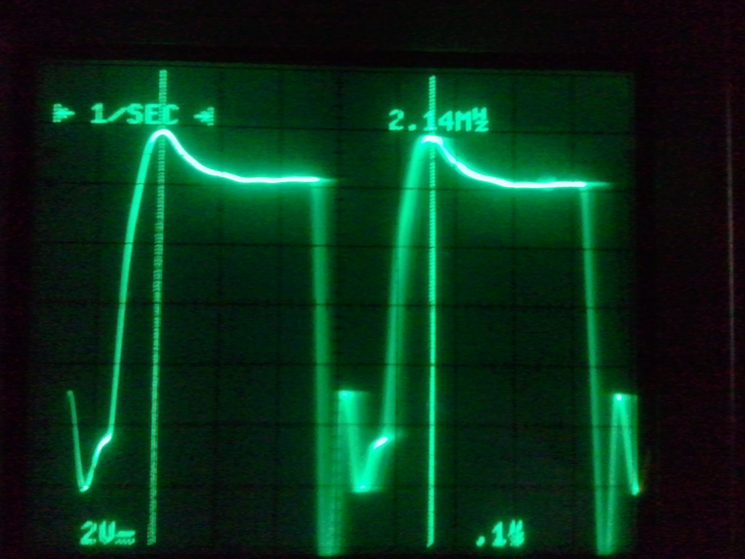
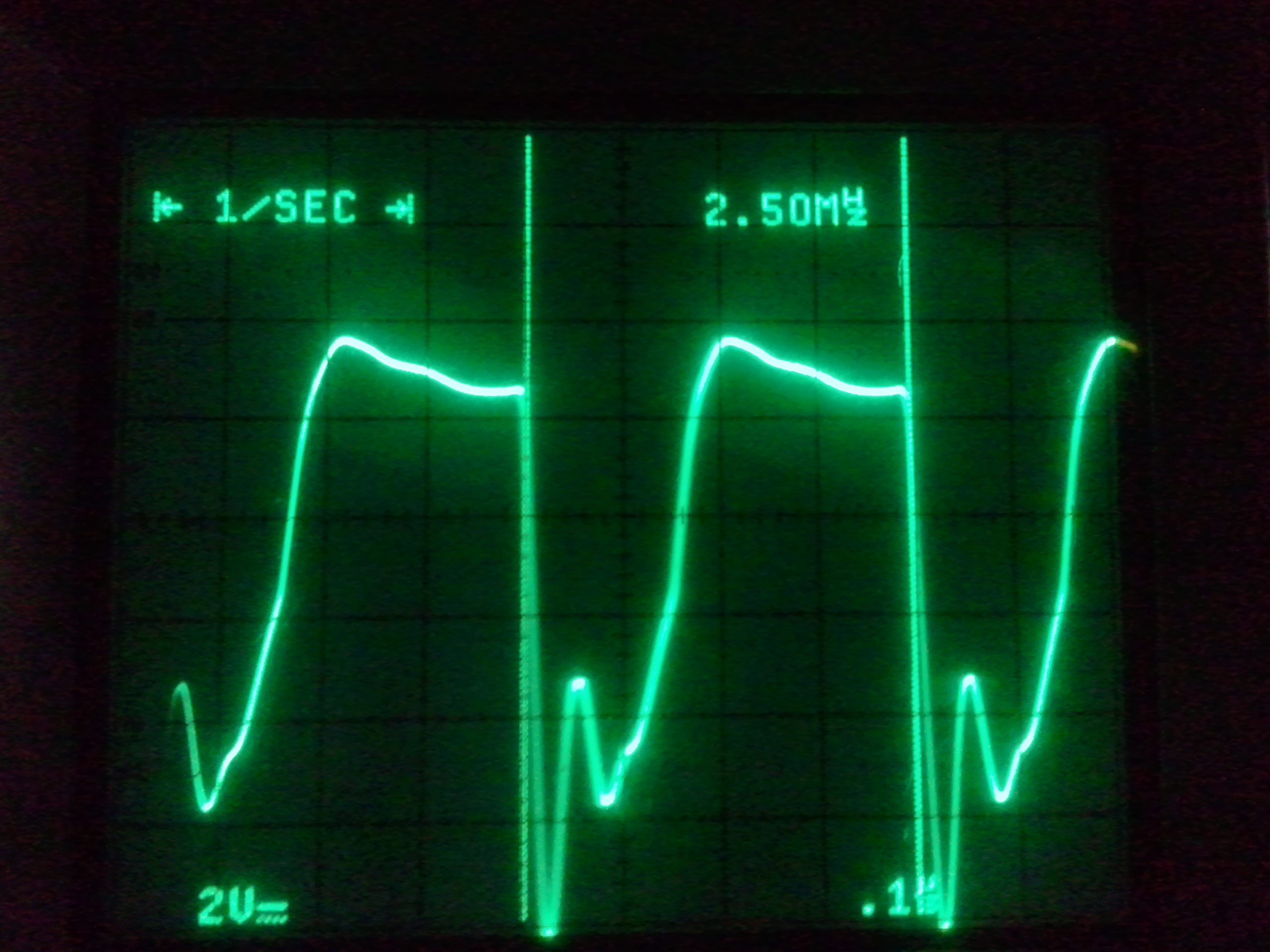
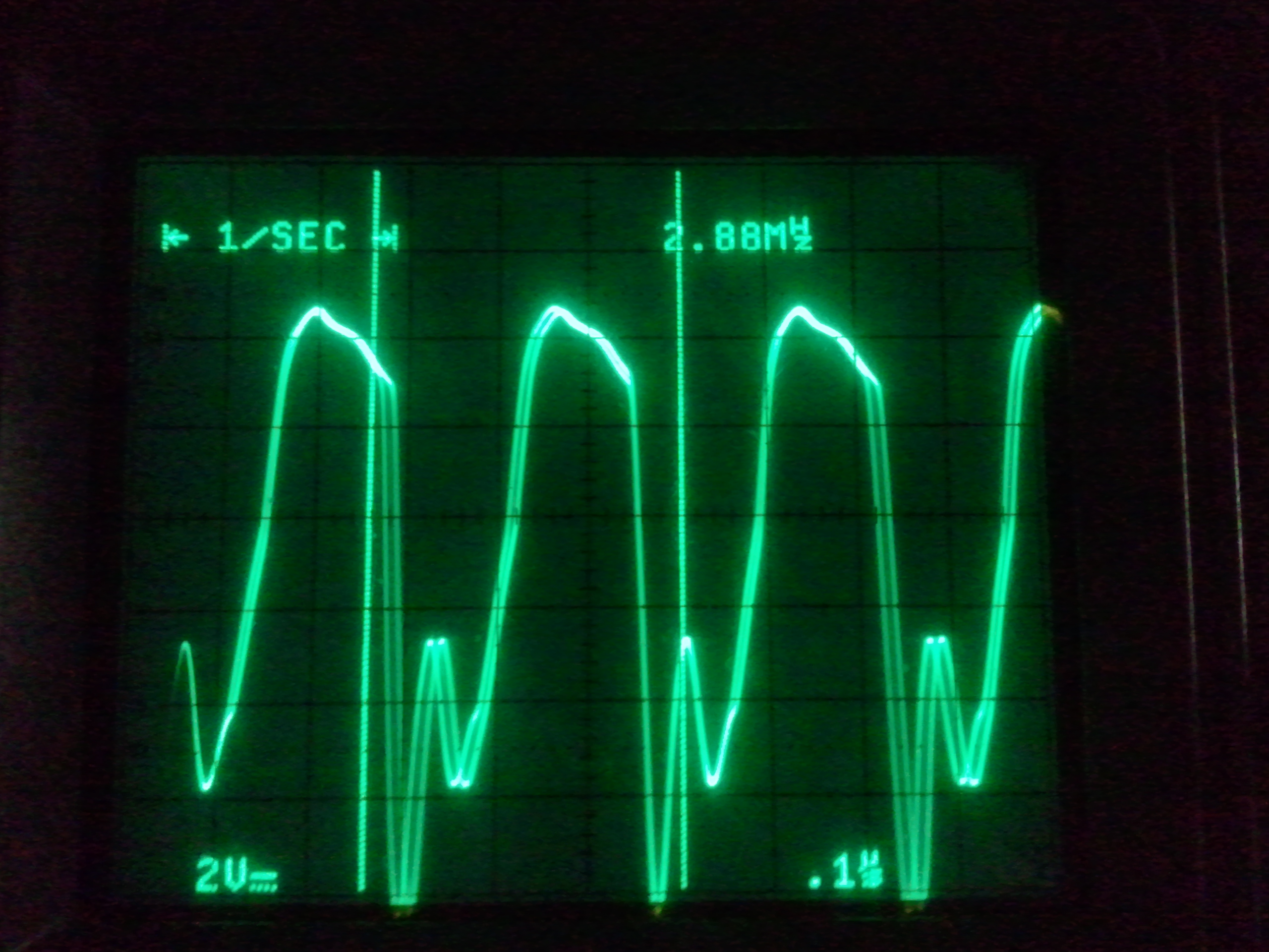
From there, voltages and resistor values were tweaked and capacitors replaced (and eventually removed altogether!); screen captures were made at 2.14, 2.50, and 2.88 MHz…

2.14MHz

2.50MHz

2.88MHz

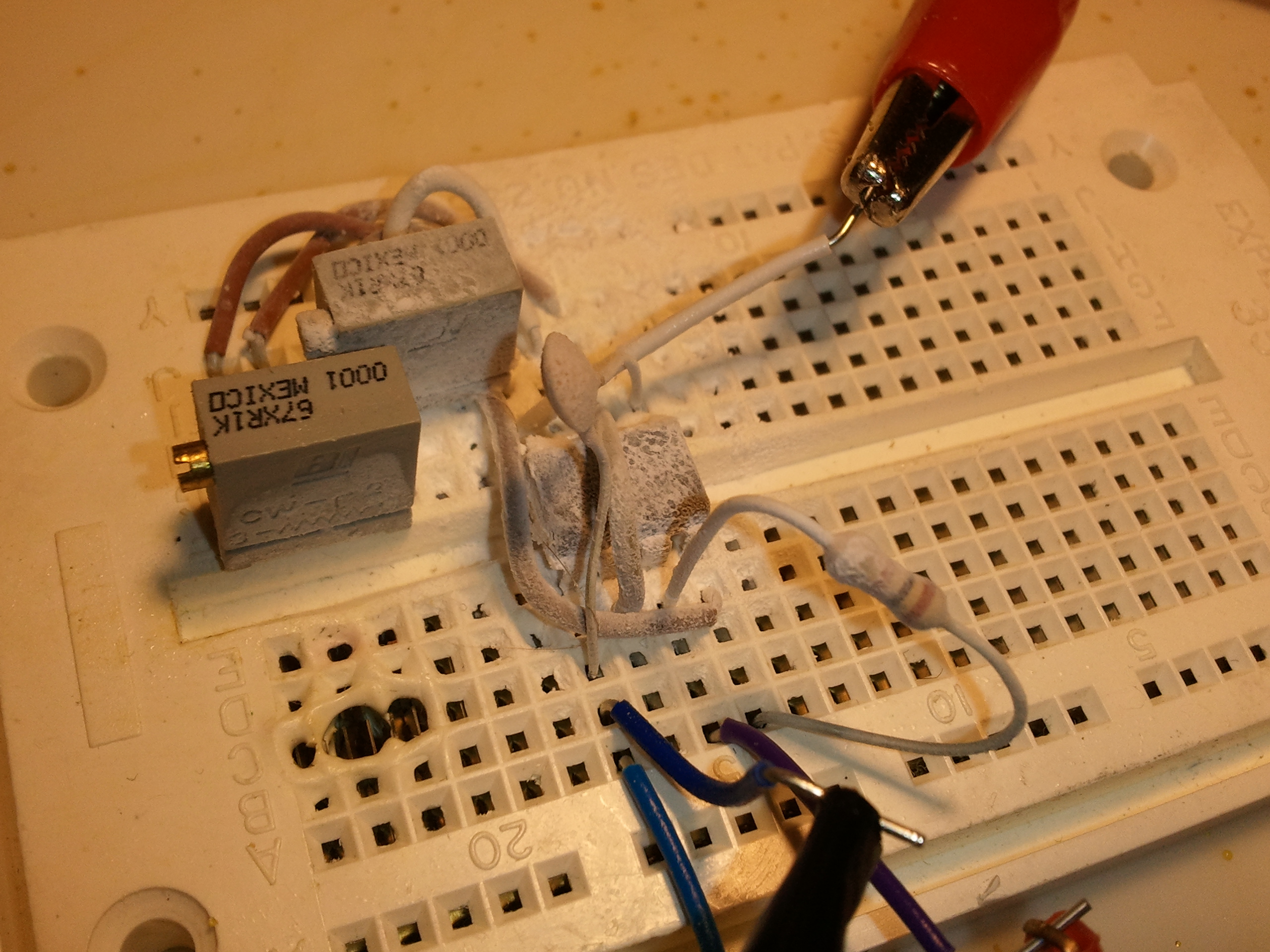
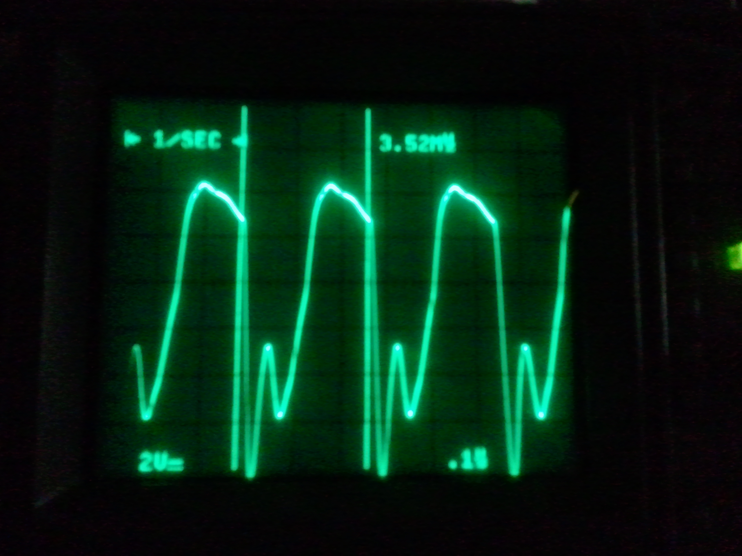
Finally, I decided to see what effect subzero cooling would have on the obtainable frequency. A few blasts with the compressed-air can turned upside down, and the 555 circuit was nice and frosty. A few more tweaks while running this cold — and voilà: 3.52MHz! (See screenshot).


A very cold 555. (The crater at lower left is from a previous misadventure involving way too much current running through a transistor.)

Note the lack of the usual astable-mode capacitor from Pin 6 to ground. Only the control capacitor on Pin 5 is present; stray capacitance is used as an active component(!) This was discovered by mistake; I was switching out the astable-mode capacitor, and found that it kept right on running with no capacitor at all (other than the breadboard connections, wires, leads, etc.)

3.52MHz

As with any overclocking venture, your mileage will certainly vary. Running this far outside of spec, the results obtained will depend on the particulars of the exact 555 you’re using. So far, I’ve only tried this — and even then, only briefly — with one randomly-chosen 555, so my guess would be that a fair percentage of NE555s can be overclocked at least this well.

Another caveat, of course, is that my only criterion for “success” was frequency of oscillation as measured on my Tektronix 2246 ‘scope. I haven’t tried to actually clock anything from such an overclocked setup.

Posted in 555, Analog, Digital, Electronics, Nostalgia | Leave a comment