Good (Geek) Books

Digital Design is fun and relatively easy, but nobody is born knowing this stuff. At some point, it’s helpful to have good reference materials. Here are links to several books, datasheets, websites, and other resources — both on Digital Design and on other interesting topics — that I’ve found helpful and/or fun to read over the years.

Disclaimer: The book URLs link to Amazon, and they offer me a small commission for purchases made through these links, but I do personally use (and recommend) each of these books — whether you buy them on Amazon, read them in the local library, find a copy at a local bookseller, or borrow them from a friend. Amazon has always seemed to provide good service for me, and I can recommend their services — and these books — without hesitation.

The Art of Electronics
(Horowitz & Hill) 

An excellent guide to introductory electronics, including both circuit theory and practical tips and tricks. Definitely recommended if you will be designing electronic circuits.

The C Programming Language
(Kernighan & Ritchie) 

This is the book on C programming. C geeks refer to it simply as “K&R”. (I actually have the first edition of this one, but plan on upgrading to the second edition shortly.)

Chaos
(James Gleick) 

This isn’t a book on engineering, but a fascinating discussion of the emerging science of chaos / dynamic systems. Chaos is (very roughly) the study of how small inputs to a system can end up having large-scale effects.

(link) The Z-80 Microcomputer Handbook
(William J. Barden) 

This is an excellent guide to both connecting and programming a Z80 CPU. It shows the various connections that need to be made to the address, data, and control busses, along with an explanation of how these control pins operate. In addition, it serves as a good introduction to Z80 assembly programming. I used this book almost exclusively when designing and programming the DrACo/Z80. It’s a great one-stop resource for getting started with Z80s.

The Road to Reality
(Roger Penrose, Ph.D) 

This book is essentially a complete college Physics curriculum in one book. It takes readers from a basic understanding of math (starting roughly with fractions), up through many of the concepts encountered in modern physics. It’s over 1,000 pages, the first 300 or so of which serve as a course in the mathematics that is needed for the rest of the book. The first hundred pages or so are relatively accessible (depending on your math background), and the material becomes more challenging and more interesting from there. It’s definitely a book to be read a few pages at a time.

BASIC Scientific Subroutines (Volumes I and II)
(F. R. Ruckdeschel) 

These books contain many useful scientific subroutines. Even if your language of choice isn’t BASIC, the programs are easy enough to read, and can be readily translated into more modern languages such as C/C++.

Programming and Customizing the PIC Microcontroller
(Myke Predko) 

This is a good introduction to PIC microcontroller programming. While Microchip’s freely-available datasheets do have pretty much everything you need to know — and are a good primary resource — in-depth, tutorial-oriented books like this make it much easier to get started with PIC programming.

Posted in C, Coding, Digital, Electronics, HOW-TO, Math, PIC Microcontrollers, Science | Leave a comment

What’s the frequency, PECO?

I’ve known for many years that standard AC power in the US has a nominal frequency of 60Hz. This may or may not be typical coffee-table conversation material, but it’s no secret, being stated on many electronic devices produced for US use. What I didn’t know until recently was just how central maintenance of the exact design frequency is to the distribution of power: apparently, when the load increases without a proportional increase in supply, the frequency drops. When load is removed from the network (or additional power is added), the frequency rises. In addition, synchronizing all of the power sources and loads on the network requires precise coordination of not only frequency, but phase.

This begs the question — how much does the power-network frequency vary? Could you use it as reference for a wall clock? If it were a musical note, would it be consistently on-key? Could you use it as a lab-quality timebase? This calls for an investigation!

The first obstacle to this, of course, is voltage. Standard household AC power in the U.S. is 120V RMS, or ~169.706V peak, or ~339.411V peak-to-peak. (So, as high as “120 volts” sounds, that’s actually quite an understatement!) Piping this directly in to sensitive modern electronic equipment is a guaranteed way to let all of the magic smoke out — and probably start a fire, for good measure. A way is needed to reduce this down to a reasonable level.

It would be straightforward to use a transformer, but that’s not really needed here. With some precautions, a simple voltage divider will do. A few considerations are important. First, the output voltage should be relatively low — say, less than 5V peak-to-peak. Second, since small 1/4-watt resistors will be used, current must be very low — specifically, under 1/480 amp (120V RMS, times this current, must be no more than 1/4 watt.)

The second requirement means that the total resistance must be no less than (120/(1/480)) = 57.6 kilohms. To satisfy the first (voltage) requirement, the ratio between the two resistors should be no more than 1:40 or so, preferably a bit more. I ended up going with a 1-megohm and a 1-kilohm resistor; this should result in RMS current of about 120uA and an output voltage of about 120mV RMS (~339mV peak-to-peak.)

Finally, the connection order matters — at least for safety. According to US code, AC wiring is done with black and white shrouded conductors (with green present as ground, on three-conductor cords.) White is neutral (which ideally should have a voltage near Earth ground and therefore be reasonably safe to expose), and black is “hot” — the active line, which should never be exposed outside a device. Consult your local electrical codes (or better yet, get a qualified professional to help you) if you’re not completely sure of what you’re doing. High-voltage AC power can kill.

The idea is to expose only the neutral line and the (slightly higher than ground, and still probably safe) voltage-divided line. Therefore, the large 1-megohm resistor is connected to AC “hot,” and the 1-kilohm is connected to the neutral. The two output wires are connected to the neutral line and the junction of the two resistors (see schematic below.)
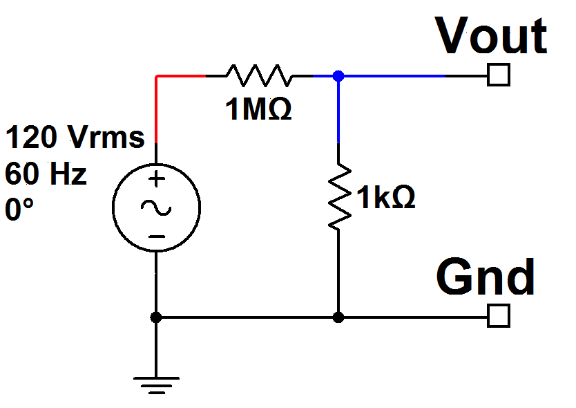
A bare-bones circuit for reducing the AC voltage. "Ground" is really the Neutral line -- which should be the white wire in the US, if your electrical installation is compliant with current US code. Don't bet your life on this, though!


If I were going to do this right (to make it into a commercial product, or to use it on a regular basis etc), it would need a few more important features. I’d consider the following a minimal list — and even then, I’m not an expert in power electronics. It might be best to go with a transformer — but I was trying to avoid using any reactive components here. For safety, I’d add:

  • A fuse in the “hot” line, just after it comes from the plug;
  • 1K resistors (or perhaps higher) in series with the Vout and Ground lines;
  • A pair of back-to-back Zener diodes connected between Vout and Ground, to limit output voltage to a safe level.

Once the “quick-and-dirty” voltage divider circuit above was built (and carefully tested several ways), I was able to connect it to a frequency counter and log the frequency of the AC power over time. Here is a time-domain graph and a histogram of what I found, along with a graph showing a few strange anomalies in the raw data…


Frequency-vs-time graph (anomalies removed.) Click for larger.


Frequency histogram (anomalies removed.) Click for larger.


Frequency anomalies. Each was far outside the 60Hz spec, and lasted for a single sample. Click for larger.

So in conclusion, the frequency appears to be extremely stable — the average (excluding the three anomalies) was 59.99907Hz, with a standard deviation of 0.02569Hz. On average, the frequency was about 15.56ppm off. Two standard deviations corresponds to roughly an 0.0856% error, or 856 parts per million.

If you were to set a clock by the 60Hz timebase (and some mechanical clocks, at least, do use this method), it would probably gain or lose one second every 17 or 18 hours, if it were to have a low-pass filter to ignore the anomalies (and mechanical clocks would inherently be unaffected by these.)

The frequency ratio between two musical notes (in the chromatic scale common in Western music) is 2^(1/12). If 60Hz were the desired frequency of a musical note to be played, the next half-step up would be at ~63.567786Hz. This is about 138 standard deviations. (Assuming a Gaussian distribution, as suggested by the histogram above, this essentially means such a value would never happen in the expected lifetime of the Universe, and then some.) This also approximately corresponds to the “just-noticeable difference” between two pitches — meaning that the difference in frequency would have to be at least this much to be perceived by most people as different from 60Hz. In other words, the 60Hz of the AC power network is, musically, quite pure indeed.

The anomalies call for more investigation. About every eight thousand samples, a single sample appears with a count far outside the Gaussian distribution otherwise seen. To call these anomalies “outliers” would be a huge understatement; the smallest of these is hundreds of millions of standard deviations away from the mean. Clearly, another phenomenon is at work here. Could PECO be encoding periodic data in the power? If so, what are they saying??


Posted in Analog, Digital Citizenship, Electronics, Power, Science | 2 Comments

Core II, The Paleotech Way

At its core (pun intended), Paleotechnology is really about rediscovering old technological methods and documenting them for future use. Just as archaeologists and paleontologists might piece together the history of a forgotten village based on buried pottery shards and the remnants of old buildings, paleotechnology concerns itself with rediscovering the way engineers made things work, years ago.

A good example of one technology that is becoming increasingly difficult to find information on is magnetic-core memory. Since, with core memory, there is a more-or-less fixed amount of construction effort required per byte of capacity (I.E. someone has to thread all those wires through all those cores), Moore’s Law doesn’t apply. For that reason, core memory (with its relatively constant cost-per-byte) was long ago surpassed by RAM and later technologies such as Flash memory.


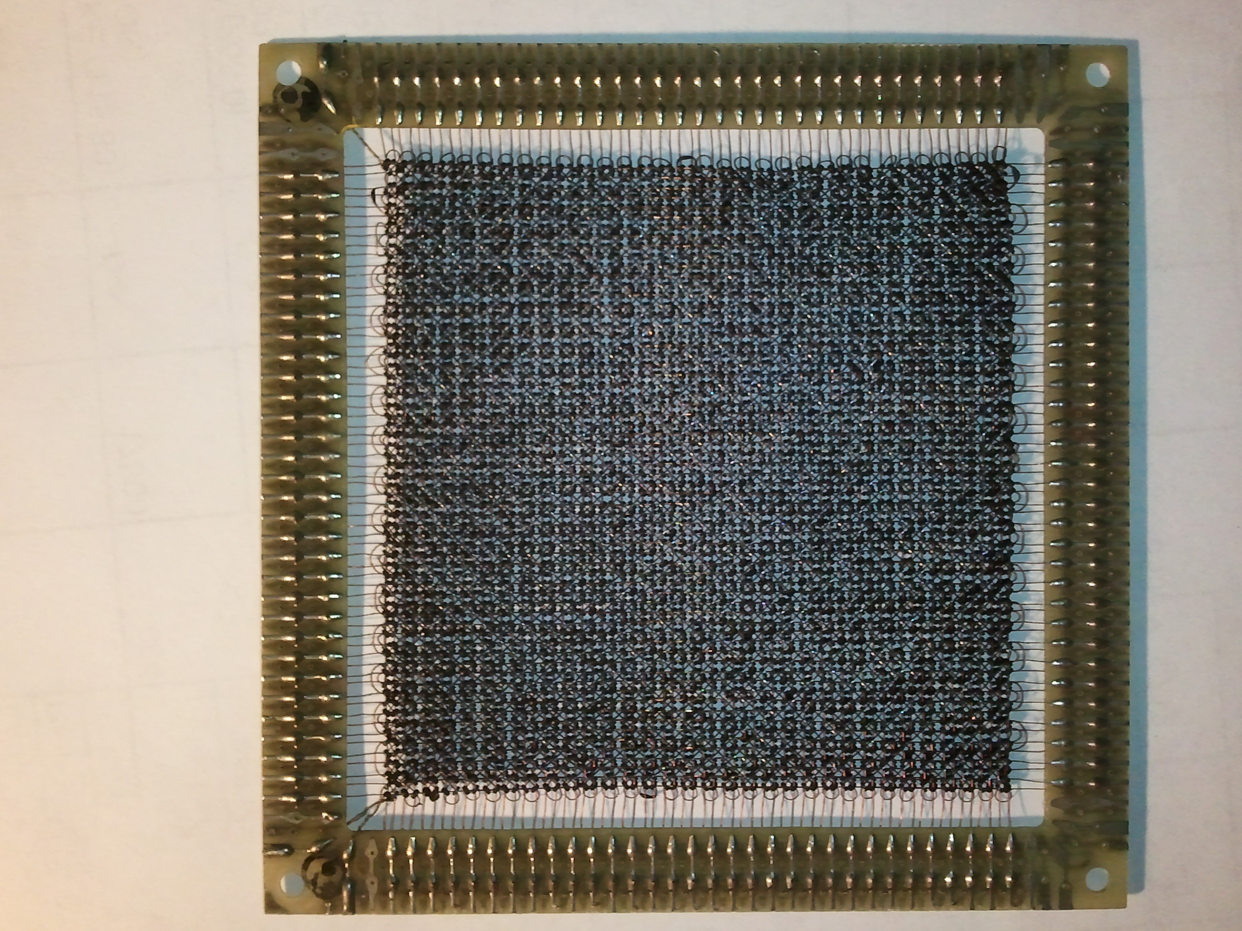
A 64-by-64 plane of core memory: half a kilobyte! (Click for larger)

Core memory stores bits in an array of ferrite cores — tiny rings made out of a ferromagnetic material which can be magnetized in one of two directions. Passing a large enough current through the core in one direction can record a “1”; passing a large enough current through the core in the opposite direction records a “0.”

The contents are read back via a destructive-read process: a “0” is written to the cell to be read. If the core was magnetized in the “1” direction, a small electrical pulse will appear on another wire passing through the core. If it was already a “0,” no pulse will appear (since writing a “0” didn’t change the magnetization of the core. What made core memory practical was an ingenious method of combining the currents from two different directions in order to select only one bit in an array.

The key observation is that a certain amount of current is needed to change the core’s magnetization. If only 60% of this current is used, the magnetic direction won’t change. Therefore, two wires can be passed through each core in an array: one for each row of bytes and one for each column. To write to a bit of memory, drive both the row and column lines in the correct direction, each with 60% of the critical current. Only the correct bit (at the intersection of those two wires) will be affected, since other bits will receive at most 60% of the critical current. (A third “sense” wire is threaded through many or all of the cores; the “sense pulse” that results when a “1” is converted back to a “0” is read out on this wire. This is the diagonally-threaded wire visible in the photo.)

This much theory is relatively easy to find online. The tricky part, I found, was in the details. How much current isthe right amount? Are we talking microamps, milliamps, or whole amps? I had found a plane of core memory (pictured above) on eBay a while ago and bought it with the intent of bringing it back online as a demonstration. What I didn’t want to do, though, was burn it out by using too much current.

Last quarter, I finally found the next few pieces of the puzzle. The professor teaching a course I was taking mentioned that the critical current was around 500mA.  He also provided the title of a book with more details on the workings of core memory. I’m not sure why core memory is still being discussed in computer engineering courses in 2011, but I’m not complaining!

So, with this new information, I am beginning “Project Core II.” (The II referring to a second career for this particular plane of core memory.) Here’s the plan:

  • Using an ohmmeter, test all 64 horizontal and 64 vertical wires, and the sense line for continuity. (DONE: everything seems fine!)
  • Pass a wire through one “bit” of core memory (I found a bag of ferrite cores on eBay, too.)
  • Pass increasing amounts of current pulses through it and see if I can sense pulses on a second wire.
  • Once the pulses are observed, characterize what amount of current is required to make this happen.
  • Try using a pair of wires to produce a combined current, and characterize what amount of current is required to drive the core using this method
  • Try the above with several cores on a wire in one direction and a separate select line for each.
  • Make a holder for the core memory plane, probably in the 3D printer. (I’d rather not solder directly to such a cool museum piece if I can help it.)
  • Try sending pulses through the actual plane of core memory, starting out with low current values, and characterize what drive current is needed.
  • Make a driver circuit (using a PIC and current-source circuitry) to store two or three bytes of information on a string of cores.
  • Expand the driver circuit to cover all of the lines in the plane of core memory
  • Design a nice interface for the thing and package it in acrylic as a demo piece.
  • Run automated test patterns to check for various error syndromes.
  • Perhaps design a simple PIC webserver, using the core as document-storage RAM!
Posted in Core Memory, Digital, Electronics, Nostalgia, Science | Tagged , , | 2 Comments

Magic Carpet Ride (Segway review)

One of the nice things about working at a university is that there are all sorts of cool presentations, demos, and the like happening around campus throughout the year. Last week, Segways were available at the Armory for faculty, staff, and students (and probably anyone else who wandered in and looked interested) to try.

Although I’m by no means a control-systems expert (I have some basic understanding of PID controllers and am dabbling in aircraft autopilot design as a hobby), I know enough to know how difficult the problems are, given all of the nonlinearities and possible chaotic interactions involved.

Segways work by a computer-controlled dynamic balance system; the rider stands on a platform between two wheels, and electric motors provide propulsion and balance. That’s the theory, anyway — but I had always wondered how well it worked, in practice.

...Who's supporting whom here, Dad?


A while ago, my parents had taken a Segway tour of Richmond; they said they enjoyed it a lot, and that the Segways turned out to be fairly easy to use. (That’s them in the picture.) I figured if my folks could do it, I had no excuse (being thirty years younger and having a much better understanding of the technology involved), so I headed over to the Armory to try riding one myself.

Segways at the Drexel Armory

I’m very glad I did! Although as with any new activity, there is a short learning curve, after five or ten minutes, riding a Segway becomes quite intuitive. Shift your weight forwards a bit to accelerate, shift your weight back to brake, and pull the handlebars gently left or right to steer. Here are some observations from a quick test-run around the Drexel Armory:

  • Relax a bit and try to trust the Segway to maintain balance. When I first stepped on, the Segway’s balance control and my own reflexes briefly set up an oscillation, with both overcompensating for the other. Once I held still, the Segway settled right down.
  • Give yourself time to decelerate. Segways can go up to 20km/hr or so (~12.5 mph), which takes a bit of getting used to; you may need more room than you  think to slow back down. (They also seem to have a set maximum deceleration rate, so as not to cause the rider to do a faceplant.)
  • Dismounting is relatively easy. The sailor’s admonition to “step lively” applies here. (Who’d have thought that an afternoon learning about sailing would have applications in robotics? Thanks, Dr. R!) Come to a stop, continue to hold the handlebar, and step backwards off the platform.
  • Don’t let go of the handlebar when dismounting (hold the Segway upright once you dismount.) The Segway trainers said that, without a rider on board, the Segway could fall over. This seems unintuitive, but I took their advice anyway.
  • Have fun! Once you get used to it (which doesn’t take long), it feels like you’re riding a magic carpet — or perhaps like surfing?

Finally, here are the answers to the questions I had before trying a Segway:

  • Do they really work? How easy are they to ride?
    • Yes, they work. Riding one is much easier than riding a bicycle or rollerskating. Give yourself ten minutes with a Segway trainer; that’s all you’ll need.
  • Why not just walk?
    • For one thing, they’re much faster than walking — as long as conditions support it. They are a bit less maneuverable, but not to the extent you’d expect; they should be able to go anywhere a wheelchair can.
    • They’re a lot of fun, and the technology is amazing!
  • Do you need to have a good sense of balance?
    • No. I’m sure it doesn’t hurt, but I’m a typical (non-athletic) geek, and I did fine. Anyone able to learn to rollerskate or ride a bicycle (even if you haven’t yet) should have no problem on a Segway.
  • How much do they cost?
Posted in Analog, Digital, Digital Citizenship, Electronics, Robotics, Toys | Leave a comment