LEDs as input devices

LEDs are fairly straightforward to use — just put them in series with a current-limiting resistor and apply forward voltage to produce light of whatever color the LED is designed for.

What isn’t as well-known, though, is that LEDs can also be used as photodetectors, sensitive to the color of light that they emit. This is a somewhat nonstandard use of an LED, but requires no more components than a standard blinking-LED project — an LED, a current-limiting resistor, and a microcontroller.

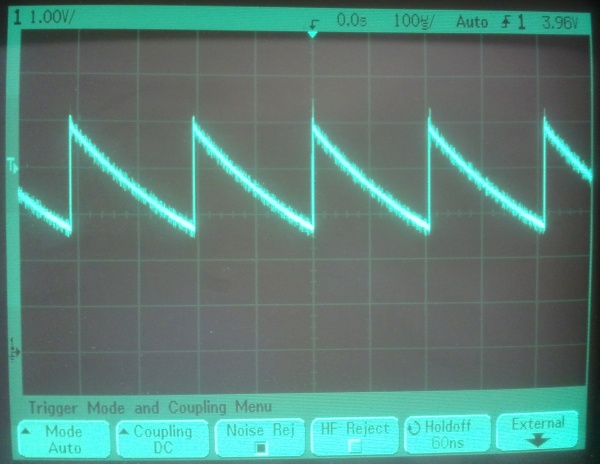
The trick is to run the LED backwards, reverse-biasing it for a short time (a microsecond is more than enough) — then disconnect the input (tristating the microcontroller I/O pin), and time how long it takes for the voltage to be reduced to below the TTL low threshold. Some leakage current will flow across the LED even in darkness, lowering the voltage towards zero with a time constant on the order of perhaps a few hundred microseconds. When brightly illuminated with light of the correct wavelength, however, a much greater photocurrent will flow, lowering the voltage on the pin in a few tens of microseconds.

In practice, this allows for a fairly straightforward recipe for detecting bright light of the LED’s wavelength (or shorter):

  • Connect the cathode (negative lead) of the LED to an I/O pin
  • Connect the anode (positive lead) of the LED to Ground via a resistor
    (Yes, this is intentionally backwards from how LEDs are usually used.)
  • Program the microcontroller to do the following in a loop:
    • Enable the I/O pin as an output, and bring it high
    • Disconnect (tristate) the I/O pin (no delay is needed)
    • Wait for about 200us
    • Do a (digital) read on the I/O pin
    • If the pin is low, the LED is receiving bright light.
    • If the pin is still high, the LED is in relative darkness.

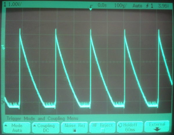
The difference in the discharge curves is easily seen on an oscilloscope…

The discharge curve under ambient light. (Click for larger.)

The sharper discharge curve when illuminated by a laser pointer. (Click for larger.)


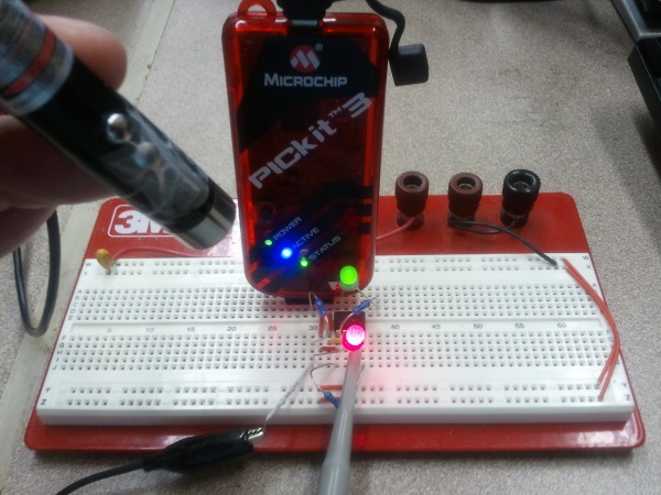
Here’s the setup I used for testing. A PIC12F683 is used to provide the initial 5V pulse. The PIC then waits for 200us and reads the TTL value on the I/O pin. If it is low (meaning the LED is illuminated), it turns on the green LED via a second I/O pin. If it is high (meaning the LED is relatively unilluminated), it turns the green LED off.

The experimental setup. A laser pointer illuminates the red LED, causing it to discharge quickly. The PIC measures this and turns the green LED on. (Click for larger.)

Posted in Components, Digital, Electronics, Hacks, HOW-TO, PIC Microcontrollers | Leave a comment

TTL debugging techniques

It happens all the time, even to experienced professionals. You wire up a digital logic circuit, but it doesn’t work the way you expect. Here are some of the most common reasons why a digital circuit might not work, along with tips on how to diagnose the problem.

Check the chips’ power…

  • Is the proper power supply (typically 5VDC) connected to each chip?
  • Is Ground connected to each chip? Is it at 0VDC?
  • Are power and ground connected to the correct pins?
  • Is the power reasonably clean? (Check it with an oscilloscope.)

Check for common wiring mistakes…

  • Are any pins on the chip left unconnected? If so, should they be?
  • Are any of the chip pins bent underneath it, instead of making contact?
  • Are enable pins connected and tied to the correct value?
  • Are any outputs shorted together? (This is a Bad Thing™)
  • Are any outputs tied to power or ground?

At this point, take a logic probe and start tracing signals on chips that seem to be misbehaving. Follow the “contract model” of diagnosis: You provide power, correct signals, correct power, and an output of sufficiently high impedance, and the chip performs the correct function. If it doesn’t, and your conditions are OK, replace it!

Posted in Design, Digital, EET205, EET325, Electronics, HOW-TO | Leave a comment

Rediscovering Vacuum Tubes, Part 1

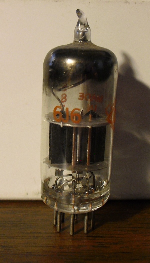
A while back, I bought several 6J6 vacuum tubes (dual triodes with a common cathode) on eBay, thinking that it would be an interesting project to wire them up and make an amplifier or something from them.

A 6J6 dual-triode vacuum tube (click for larger.)

Vacuum tubes work via the “Edison effect,” also known as thermionic emission. A hot filament (or a negatively-charged plate heated by a filament) will emit electrons into a vacuum. The flow of electrons can be increased and directed by drawing them toward a positively-charged plate. This combination of filament, vacuum, and plate forms a vacuum diode (since electrons will readily flow from the cathode to the plate, but not the other way around.)

With the addition of a negatively-charged grid between the filament and plate, the flow of electrons can be regulated by a relatively small signal. This allows amplification of an electrical signal, and makes possible amplifiers, oscillators, and even digital logic.

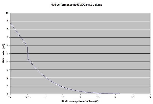
There is a nonlinear relationship between grid voltage and plate current, though. Some investigation was called for. The 6J6 is a dual-triode device, with a heated cathode, two grids, and two plate anodes. The two sections can be connected electrically in parallel (the grids tied together and the plate sections tied together.) I decided to initially test it in this configuration. Varying the grid voltage while measuring the plate current, I came up with the following performance graph:


Plate current as a function of grid voltage, for a 6J6 at 50V plate voltage. (Click for larger.)

The anomaly at roughly 0.5V grid voltage bears further investigation. While decreasing the grid voltage systematically, the plate current seems to have jumped quickly from about 4.4mA to 5.9mA. My guess is that the increasing current in the tube caused the dynamics to somehow shift to another mode of operation. I suspect that slowly decreasing the grid voltage may uncover a hysteresis curve.

Perhaps this could even be used as a way to store a single bit of memory. If so, this has amazing, profound implications for the future of tube-based computing!

This post is dedicated to the memory of my grandfather, Millard C. Carr, who would have been 95 years old today. We miss you, Granddad.


Posted in Analog, Digital, Electronics, HOW-TO, Nostalgia, Power, Science | 4 Comments

Freestylin’

Just about the only thing better than a nice cold soda is a nice cold free soda. It’s even better when it’s a nice, cold, custom-selected, free soda from one of the new Coke Freestyle vending machines.

A Coke Freestyle machine. (Click for larger.)

But perhaps I should explain about the “free” part.

Since I worked an earlier-than-usual schedule today, I was able to make a Geek Pilgrimage to Moe’s Southwestern Grill in Suburban Station. I’m not usually one for authentic Tex-Mex (I’m sure it’s very good quality, but the spices would kill me). This particular Moe’s, though, had one of those new Coke Freestyle custom soda vending machines. I’d seen it through the store window while passing by after hours and had meant to try it. I researched it online and found that it custom-mixes each drink — not only from syrup, CO2 and water like normal soda fountains, but from an inkjet-printer-like assortment of dozens of flavors that it can mix in over a hundred combinations.

I stopped by Moe’s today and ordered a drink. When I got to the machine, though, most of the selections were grayed out — empty. This was unusual; I wouldn’t have been surprised if one or two were sold out, but it seemed that every good drink was out of stock.

This is the part where it pays to be a geek. I’d read about these machines online and found a video describing an Easter egg in the “Water” menu — a secret way to pull up the maintenance menu. I tried it, and it worked.

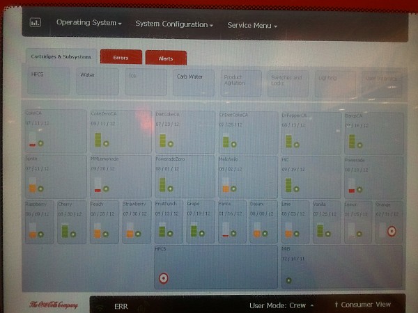
Surprisingly, the machine seemed to have enough syrup for Dr. Pepper, Coke, Barq’s, and several other good drinks. What it didn’t have, according to the supply screen, was “HFCS” (High Fructose Corn Syrup.) AHA. No sweet stuff == no way to make any of the good drinks!

The "secret" maintenance screen, showing a lack of HFCS. (Click for larger.)

The shift manager who was looking at the machine with me checked in the back, and said that it had a full box of HFCS. Apparently nobody had told the machine this, though. I poked around a bit more and found a resupply menu. A quick reset later, and the consumer menu was lit up correctly once again. The manager, grateful for the help, let me have my drink on the house. I’ve never enjoyed a Fanta Lime soda this much before. Maybe that’s because I’ve never had a Fanta Lime soda before.

It’s good to be a geek.


Posted in Current Events, Digital, Digital Citizenship, Reviews | 2 Comments