JLCPCB

The Maker revolution generally encourages adding to the repertoire of processes that can readily be done at home. Desktop soldering stations, multimeters, and power supplies have been available for decades; oscilloscopes have been getting more affordable recently, and the recent explosion of 3D printer technology has really made a lot of things possible.

The production of good quality circuit boards, however, is still a challenge. I can produce more-or-less-acceptable 2-layer boards on our LPKF PC board mill at work, but producing good circuit boards at home either requires a lot of patience and toxic chemicals or a circuit board mill costing probably into four figures. And even then, the boards produced lack through-hole via plating, solder mask, and silkscreen, and are generally cruder and less reliable than any industry standard. Some processes still require expensive equipment to do well.

Some circuit boards, freshly milled on the LPKF desktop mill at work.

Recently, however, a number of DIY-friendly, low-quantity solutions for getting PC boards made have become available. I recently placed an order for ten PC boards with JLCPCB.com. Here’s how that went, and why I now have another go-to vendor for my list of favorites.

The process starts by creating a set of Gerber files. This is usually done automatically by PC board CAM software like Eagle CAD. I’ve been using FreePCB for years to make our boards at work, so I decided to see how it did.

CAD view of the top of the board

The test board (which needs several revisions, but that’s expected) is mostly a 24VAC-to-5VDC power supply for a Raspberry Pi and relay module, along with some extra connections to make hookup easier. I created the design in FreePCB, exported the Gerber files, and then uploaded the design to JLCPCB’s site. Design took a few hours; the upload and ordering process took maybe half an hour since I was unfamiliar with it. Now that I’m signed up and everything, future orders will probably take more like ten minutes.

…and that was it, really. I got a couple of emails later that day saying the boards had started production (even though it had to have been something like midnight in Shenzhen.)

Less than a week later, an express DHL shipment arrived. The boards look quite good, especially considering I paid $2.00US for the whole ten-pack. Shipping was just under $20, but that’s expected for essentially overnight shipping from China.

Ten boards, delivered in about a week, for $20 or so. Not bad.

I populated and soldered the first one off the stack (I only really needed one, but it’s the same price for ten), and it works well so far. Custom good-quality PCBs for twenty cents each (plus shipping). I love living in the future.

Posted in Electronics, Resources | Tagged , , , , , | Leave a comment

OpenSCAD

The traditional way to create models for 3D printing is to design them using a CAD program. Typically, the designer will draw a few rough shapes to build the basic outline of the part, extrude them, then add other features and/or remove material for holes, bezels, cutouts, etc. This works well for many designs, and is deservedly by far the most popular way of creating 3D models. However, it’s not the only available method. Creating models in code, from mathematical operations, opens up design possibilities that would be difficult or impossible to reproduce manually.

If you want a hole in your model, for instance, it’s generally straightforward enough to draw a circle and extrude it into the material. But if you want four hundred of them in a 40×10 matrix, that could take a while. And smooth, mathematical designs like a Moebius strip can be nearly impossible to create by hand.

A Moebius strip and the code to produce it in OpenSCAD. (Click for larger.)

OpenSCAD is a Free, Turing-complete modeling language for the creation of 3D models based on mathematical primitives. Basic shapes such as cubes, spheres, and cylinders can be scaled, translated, rotated as well as added to, subtracted from, and intersected with other objects. Control structures such as for loops allow for the automatic assembly of more complex objects like corkscrews based on the mathematical formulas. Define the shapes, and OpenSCAD creates the model.

Printing your creations is straightforward. After finishing the code for your design, press F6 to render your design (using a more accurate method than the quick preview). Once rendered, the design can be saved as an .stl file to be sliced into g-code by the slicer of your choice.


Posted in 3D Printing, Coding, Math, Tools | Tagged , , , , , | Leave a comment

Mystery Resistance

As part of a recent Girls, Inc. summer camp activity we hosted at work, I designed and produced about a dozen Electronic Mood Rings. This turned out to be a learning experience in many ways.

The prototype Electronic Mood Ring.

I learned that, while SMT devices are tricky to work with, SOIC parts can be reasoned with if you use a good iron, silver-bearing solder, and generous amounts of flux.

I learned that 1206 SMT parts are very forgiving but still a pain to solder by hand. Stencils and reflow may be the way to go, here. Or just outsourcing it.

I learned that PIC12F1571 microcontrollers should be able to run at 32MHz internal clock speed. Nice! Except that mine didn’t want to turn the PLL on, and I had to settle for 16MHz because it was easier than continuing to argue the point. Besides, the new BRW instruction means no more mucking about making sure my computed GOTO tables don’t cross 8-bit boundaries. So I can forgive a few quirks.

I learned that I still don’t know how to solder true SMT parts such as NeoPixel Mini PCBs. Might need a reflow plate for those.

I learned that, for whatever reason, clear PLA filament just will not print reliably on my machine. Purple printed fine. Pink printed fine. Blue printed fine. Even black cooperated and printed without problems, which isn’t always a sure thing. But three different reputable brands of clear filament caused 95% of the problems. It jammed. It blobbed. It strung. It refused to adhere to the bed at one point.

Bizarre.

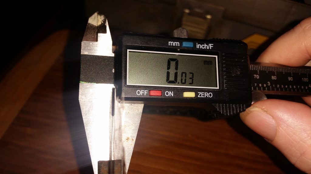
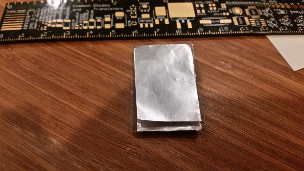
I also learned not to trust knockoff parts. The battery holders I bought only worked properly once I figured out you need to wedge a strip of aluminum foil under the negative contact, to get it to work. Pure Chinesium. Well, to be fair, they were a lot less expensive, and worked well other than that. My guess is they were tested with a different brand of battery.

The most surprising thing I learned about was the Phantom Voltage Divider.

I should explain. The battery holders I was using included a small circuit board, a CR2032 battery, a SPST switch, and metal contacts and traces. That’s it. No resistors or other electronics. Bare-bones simple.

So it was perplexing to put a 3V battery in and, with the switch off, measure 1.8V out. Changing voltages like that requires either active electronics or at the minimum, two resistors. There were no resistors anywhere on this board. What was happening?

Lack of sleep due to optimistic scheduling was what was happening. It turned out that the meter was correct. It really was reading 1.8V, and it was all my fault. Well, mine and the meter’s.

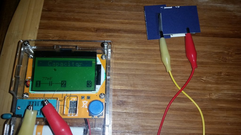
Multimeters (real ones) have a finite input impedance. This can be a calibrated high value of, for example, 10M ohms on professional desktop meters like the Agilent 34401A, or a similar, uncalibrated but high value on handheld meters. No doubt the Fluke that I was using has a well-understood input impedance. Or at least a high one.

Most of the time, this high impedance means that the meter won’t have a significant effect on the circuit voltage. What little current flows through the meter is lost in the (much greater) flow of current through the circuit.

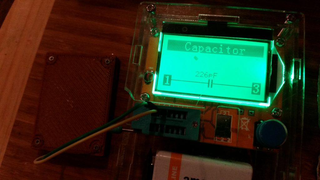
This circuit was off, though — but still read 1.8V. Due to lack of sleep, it took me a few minutes to figure out the answer. I was the missing resistor. Part of my hand was in contact with the positive terminal on top of the battery, and a few microamps of current were leaking through my hand to the meter. Since the meter had roughly the same input resistance … it and I formed a voltage divider.

The laws of physics have a sense of humor, I guess.

Posted in 3D Printing, Design, Digital, Drexel, EET201, Electronics, Fundamentals, PIC Microcontrollers | Leave a comment

Virtual Confusion

Okay, I get it. FreePCB is kind of dated and I should really learn Eagle at some point. But it’s still a useful tool — at least, when Windows doesn’t get in its way.

FreePCB, unfortunately, defaults to storing project files in a “projects” folder in its own working directory. This makes some sense, but ultimately documents are supposed to be stored in the proper place — not where the program is installed.

I agree this is best practice — but Windows (since Vista) takes things a step farther, as I found out today. If a 32-bit program is not running with administrator privileges and isn’t compiled for Vista or later, that means it can get “virtualized.”

What this means, in practical terms, is that, since Windows no longer allows programs to write to the “Program Files (x86)” directory structure, it makes a shadow copy of this structure and redirects all writes to that.

The problem arises when you want to, for example, go find these files that the program has written. They’re nowhere to be found in the “Program Files (x86)” structure — and yet, the program can exit, relaunch, and reload the files with no problem at all. Witchcraft!

Figuring that the files had to be somewhere on the drive, I went back to first principles and ran a search.

c:\>dir /s /b *.fpc

After a brief search, the files were found in the c:\Users\…\local\VirtualStore\ substructure. A quick Google search turned up the following explanation, paraphrased above.

Mystery solved. But some notice would have been appreciated, MS. Maybe one of those pop-up boxes you’re so fond of using to steal the focus at the worst possible times. Or something.

Posted in System Administration | Leave a comment