Making Music With Microcontrollers

Often, in embedded systems design, it is useful to be able to produce musical notes. A device which uses a brief, pleasant melody to announce an end-of-cycle condition, for example, can be perceived as more sophisticated — and therefore, more desirable — than one which simply beeps.

Musical notes can be produced by even the simplest microcontrollers, given a basic understanding of elementary music theory. Notes are distinguished by three qualities: frequency, amplitude, and timbre. Frequency is simply how many cycles per second are present — the “pitch” of the note. Amplitude is the loudness or energy present in the note. Finally, timbre is the quality of note (its shape, as seen on an oscilloscope). Sine waves are pure tones of a single frequency. Notes with other timbres have other, higher frequencies as additional components of their waveform.

Frequency is what makes a particular note, for example, a “C#” or an “E.” Higher-pitched notes are higher in frequency — and the notes are related by a specific formula. “Concert pitch A” (A4 in musical notation) is defined as 440Hz, or 440 cycles per second. Other notes, using the equal-tempered scale common in Western music, are defined from A440 using a specific formula.

This formula involves counting the number of musical half-steps (A to A#, A# to B, B to C, etc) between A440 and the note in question. The frequency of the new note is then defined by the following formula:

F = 440 * 2^(N/12)

…where N is the number of half-steps (positive or negative) between A440 and the new note. For example, A220 (one octave lower) is twelve half-steps down. Therefore:

F_A3  =  440 * 2^(-12/12)
= 440 * 2^(-1)
= 440 * 1/2
= 220Hz

This provides a good check of the formula, since each octave higher corresponds exactly to a doubling of frequency. (That’s why, musically, each note sounds similar to the same letter note one octave higher or lower.)

Once you have determined the frequency for a certain note, this is converted into a time period between half-cycles. For example, the 220Hz note in the example above would correspond to 1/220th of a second for a whole cycle, and 1/440th of a second for each half cycle. Doing the division results in a delay of 2.273 milliseconds for each half cycle. So, to produce a 220Hz “A,” a microcontroller program could do the following:

  • Drive the output pin high
  • Wait for 2.273 milliseconds
  • Drive the output pin low
  • Wait for another 2.273 milliseconds
  • Repeat as desired until the tone should no longer sound.

One important consideration when producing musical notes is frequency accuracy. For a note to sound correct, its frequency should be within roughly ten “cents” of the correct tone (where 100 “cents” is equal to the frequency ratio of one musical half-step.) For an ideal note frequency of 220Hz (corresponding to A3), this means the actual frequency of the note must be between 218.73Hz and 221.27Hz. The delay for each half-cycle, therefore, must be between roughly 2.260ms and 2.286ms. (A delay of 2.273ms would be nearly ideal.)

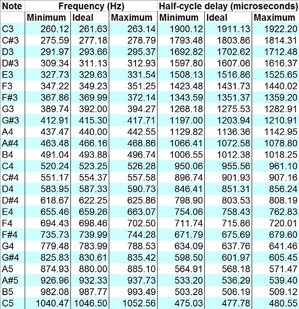
Here is a list of the ideal frequencies for each note in the range from C3 (one octave below Middle C) to C5 (one octave above Middle C), along with the minimum and maximum acceptable frequencies and the corresponding minimum and maximum half-cycle delay times, assuming an allowed tolerance of ten cents. For higher octaves, double the frequencies and divide the delay times by two. For lower octaves, divide the frequencies by two and double the delay times.

A chart of minimum and maximum frequencies and half-cycle delay times. (Click for larger.)

(Here is the original Excel file, with formulas.)


Posted in Analog, Assembly, Audio, Coding, Digital, Math, Music, Science | 2 Comments

Isochronous Assembly Code

Assembly language is great for writing really fast, efficient routines where hard-realtime timing constraints have to be met. Making a tachometer using a microcontroller running from a TTL oscillator is one example: if coded correctly, the microcontroller can be relied on to measure timing with great accuracy.

In order to do this, it is often necessary to write check-and-count routines in such a way as to make the loop execute in a fixed number of clock cycles, no matter what the current state of the count happens to be. Implementing carry logic takes extra processor cycles, so this must be compensated if the loop is to run isochronously.

On low-end to midrange 8-bit PIC microcontrollers such as the 16F88, the only available native data type is an 8-bit integer. These can be combined to produce 32-bit integers, if the next-higher byte is incremented each time the lower byte rolls back to 0x00. Done properly, the loop will always execute in the same amount of time, no matter how many of the registers roll over for a given count.

Here is the relevant portion of the code for a tachometer project I’m working on. It uses a 32-bit counter, allowing up to over four billion counts before resetting. This provides much greater accuracy than would be possible with a single 8-bit counter. The extra accuracy is worth the extra coding effort, in this case…

CycleCount:
   goto $+1

Loop1:
   goto $+1

Loop2:
   goto $+1

Loop3:
   btfss PORTA, 0 ;If A.0 is low, then
   goto HandleEvent ;skip out

   incfsz Count0, f ;Increment the low byte.
   goto CycleCount ;Low byte isn't zero. Go back to beginning.

   incfsz Count1, f ;Increment the 2nd byte.
   goto Loop1 ;2nd byte isn't zero. Go back -- two cycles later.

   incfsz Count2, f ;Increment the 3rd byte.
   goto Loop2 ;3rd byte isn't zero. Go back four cycles later.

   incf Count3, f ;Increment the high byte.
   goto Loop3 ;Go back six cycles later.

Except for the last cycle where it jumps to the HandleEvent routine, this code will always execute in 44 clock cycles. Instructions on a PIC16 always take four clock cycles (eight, if the program counter register is modified.) If Count0 is incremented to a nonzero number, execution will then pass to the top of the routine — the CycleCount: label. If Count0 rolls over but Count1 does not, execution passes to the Loop1: label, saving the two instruction cycles that were used to increment Count1. Likewise, if Count2 is incremented, control passes to Loop2: — unless Count3 is also incremented.

Since the code is constructed this way, execution will always take 44 clock cycles per loop. If the count shows one million, exactly 44 million cycles (less two cycles) will have passed since the loop started timing. This allows the system accuracy to be readily calculated — and often makes the system clock (a 50PPM, 20MHz TTL oscillator, in this case) the limiting factor in accuracy.

At 20MHz (or 5 MIPS), this code allows timing of events to within 8.8 microseconds (give or take 50PPM). Not half bad for a chip costing $1.83 or less.

Now for the hard part: implementing 32-bit integer division with a processor that doesn’t even natively do multiplication…!

Posted in Assembly, Coding, Digital, Electronics, PIC Microcontrollers | Leave a comment

Minecraft Scientific Calculator

You may have heard that Minecraft, with its various Redstone-based constructs, is Turing-complete — meaning that it can, in theory, emulate any digital computer. (The size of the Minecraft world, in fact, would make quite a few interesting designs possible.)

It’s another thing entirely, however, to see this put into practice. By combining hundreds (thousands?) of building blocks such as BCD adders and subtracters, “MaxSGB” has created an in-world Minecraft scientific/graphing calculator. Because Minecraft’s discrete 1m x 1m x 1m block system doesn’t lend itself very well to miniaturization, the resulting construct is immense — taking up millions of cubic meters of space. It gets the job done, though — just check out the video!

I’m still waiting for the ultimate Minecraft emulator, though — a computer capable of running Minecraft, inside Minecraft.

Posted in Digital, Games, Internet, Minecraft | Leave a comment

Arduino Cellular Shield

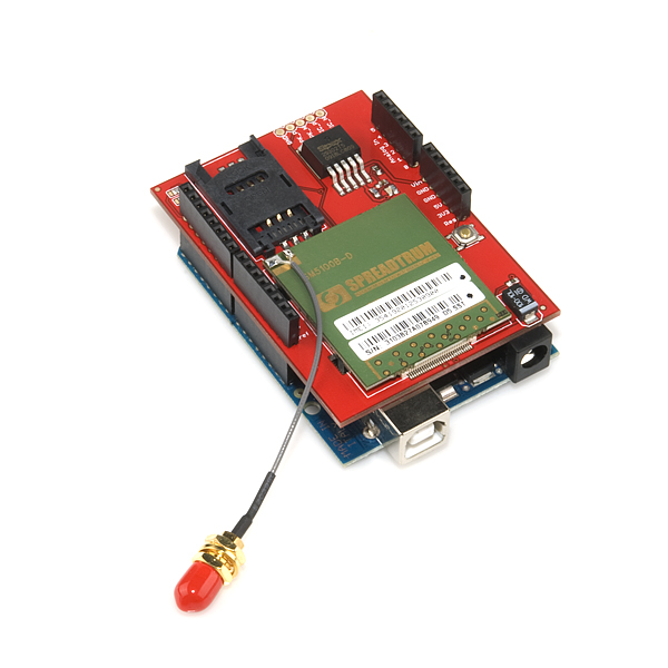
One of the few things cooler than an Arduino is an Arduino with a cellular shield. As you would suspect, this $100 shield from SparkFun gives an Arduino cellular capabilities, including the ability to send and receive text messages — and apparently the ability to place and receive voice phone calls, too. Tronixstuff has an excellent tutorial on getting started with the shield — I highly recommend it.

SparkFun's cellular shield for Arduino. (Image credit: SparkFun.com)

Here are some of my experiences getting the shield up and running with some basic, proof-of-concept sketches. I am in the Eastern US, and have had success using the AT&T network. If you are in another area and/or use another network, your mileage may vary.

First of all, in addition to an Arduino (a Duemilanove or Uno is recommended, although a Mega will work with minor tweaks) and the shield itself, you’ll need the following:

  • A cellular antenna (helpfully also sold by SparkFun)
  • A SIM card which is not locked to a particular handset (more on this below)
  • A relatively high-current 5-volt power supply (since the Arduino’s regulator isn’t rated for the amount of current — up to two amps — the shield can draw.) You can, however, backfeed the Arduino from this 5V supply quite nicely.
  • (Recommended but not technically necessary) a case to secure the shield and antenna.

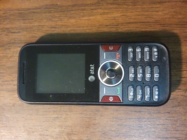
The 5V power supply was easy enough, for the time being — I decided to just use a bench supply for testing. The antenna was easy, too — I picked it up from SparkFun at the same time as I bought the cell shield. Next, I needed a working SIM card. I bought the cheapest model of AT&T “Go Phone” that I could find at the local Target. $19.95 for a cell phone — a little pricey, but I might be able to repurpose it or some of its parts.

A basic, generic cell phone came with the SIM card.

I activated the Go Phone and associated SIM card easily enough, and chose the $2-per-day unlimited calling and texting plan. (I figure that on any given day, I’ll either use the network a lot or not at all.) Texting and phone calls worked fine from the included Go Phone. When I put the SIM card in to the cell shield, connected the antenna and power, and ran through the configuration, though, I hit a problem — the “+SIND 7,” or “Emergency calls only” error. A quick search later, I found out that this was due to the GoPhone SIM cards being locked to the GoPhone handset for six months.

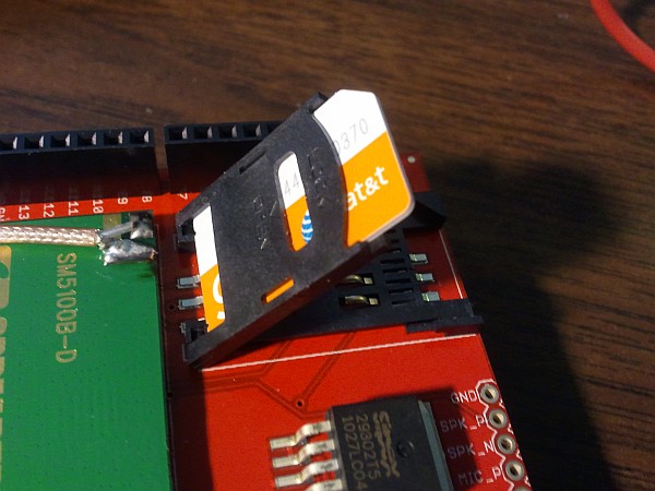
The SIM card is inserted into the carrier lid, then tilted down into place and locked. (Click for larger.)

This was not acceptable: the whole reason I bought the Go Phone in the first place was to get a working SIM card for the shield. I made a trip to the local AT&T store and explained the situation. After some misunderstanding (the sales staff out front didn’t seem particularly tech-savvy and thought I was asking them to unlock an iPhone or something), they gave me a replacement SIM card — one not locked to a particular phone, this time. I swapped the new card in, re-tried the SMS examples in the tutorial, and it worked!


Posted in Arduino, Digital, Internet | 3 Comments