In order to automate several functions at home, I am in the process of designing a low-speed home automation network. Since one of my primary goals is to have individual nodes be as low-cost as possible, I have decided on a clocked multi-master serial bus interface. Since the specifics of the interface (pullup resistor strength and signaling speed, mostly) will depend on the output characteristics of the individual nodes, some testing of a representative PIC microcontroller (a 12F683) is needed.
My testing protocol (if I can even call it that) is informal and straightforward. A capacitance, representing a conservative estimate of the capacitance of a length of RJ12 cable, is connected to an output from a PIC microcontroller. Since the network will be open-drain to avoid contention issues, a 270 ohm resistor will be used (digital outputs on a PIC are rated to source or sink 20mA max, so the pull-up resistance should be no less than 250 ohms. Power consumption is not a major concern, and a value close to the lower limit will allow faster rise times and therefore faster signaling.)
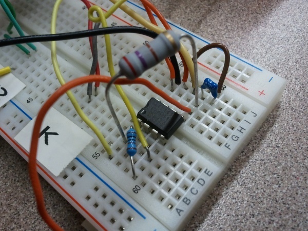
The experimental setup…
The first experiment was at full speed (running on the internal 8MHz clock): a 500ns pulse, with the pin being actively driven high and low. No capacitance was added, and no pull-up resistor was used.
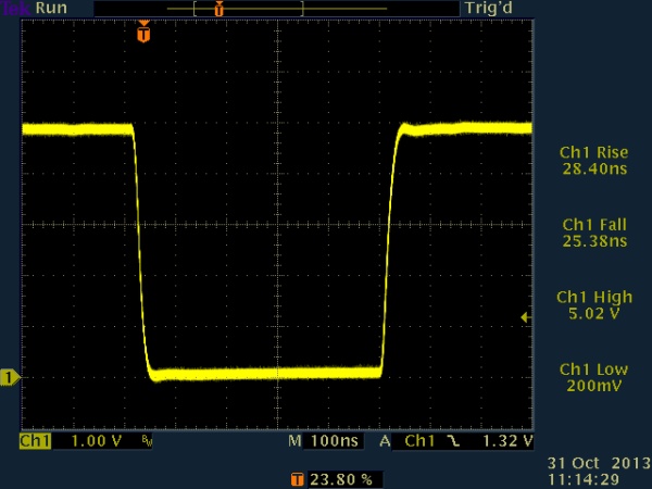
500ns pulse, no load, active high/low
Next, a 270 ohm pull-up resistor was added, and an open drain configuration was used (with the pin always either driven low or tristated, never driven high). This will prevent an overcurrent condition on the bus, should two devices assert different values at the same time.
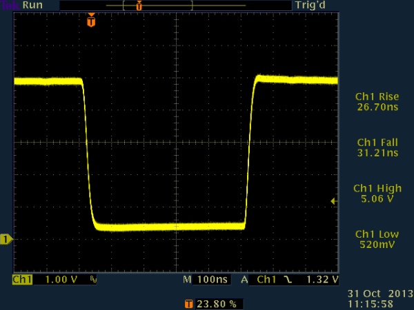
500ns pulse, 270 ohm to Vcc, active low / open drain
Next, 100pF capacitance was added. This had little or no effect on the actively-driven falling edge, but did start to affect the pulled-up rising edge.
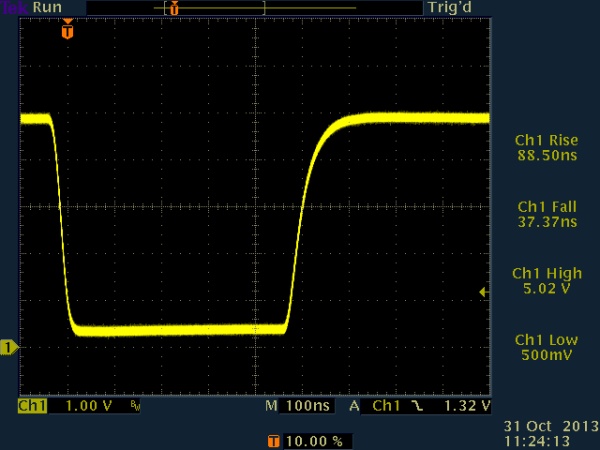
Next, the capacitance was increased to 1nF. This resulted in the voltage taking most of the 500ns pulse time to recover.
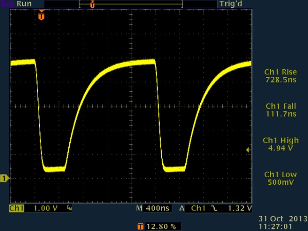
Because of this, I decided to slow the pulses down. I first tried 5us pulse widths, but the capacitance still couldn’t be increased past 1nF or so.
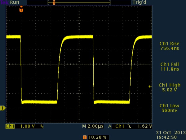
5us pulse, 270 ohm pull-up to Vcc, active low / open drain, 1nF loading
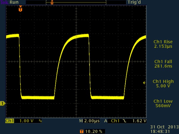
Finally, I settled on a 50us pulse time. This allows data transmission at up to 20kb/sec with a reasonably clean signal, even with 10nF loading. 6-conductor flat satin cable is stated by Black Box to have a characteristic capacitance of 22pF per foot. In standard units, this is 22pF per 304.8m, or about 72.2nF per meter. Since I plan on having about 25m of cable in the network to start (and perhaps as much as 100m eventually), this should result in a total cable capacitance of between roughly 1.8nF and 7.22nF.
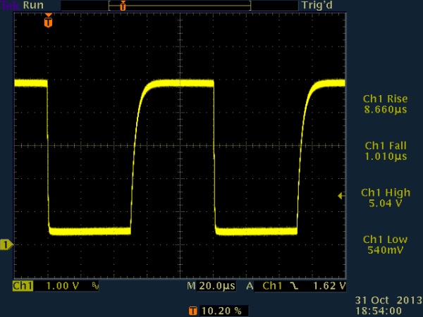
Here is a detail of the risetime at 10nF, showing a risetime of about 10us. By sampling past the halfway point of each bit period, the signal should be stable even with 10ns loading. 20kb/sec should therefore be fine. I’ll probably run it at 19,200 for nostalgia if no other reason.
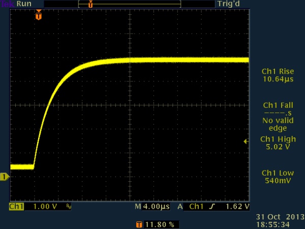
50us pulse, 270 ohm pull-up to Vcc, active low / open drain, 10nF risetime (detail)
These risetimes could, of course, have been calculated in terms of time constants (tau = RC), but it’s always nice to see actual results produced by actual hardware. One particular concern that I had was whether the PIC’s tristate functionality could really be relied upon to work this way, rather than as a relatively slow way to set up pin functionality upon initialization. It does indeed work nicely — apparently just as fast as actively toggling bits (although controlling both tristate and pin value would require swapping memory banks, which takes a few cycles.) For this test, the software simply remains in the TRISIO bank.


