The SIGMA walking robot (which I’ve written about before) is now a bit closer to completion: a wireless control link (via Bluetooth) has been added, allowing the robot to be “driven” using an Android smartphone. Links for the source code, schematics, etc are given below; email me or post a comment if you have any questions.
Here’s a video of the robot in action:
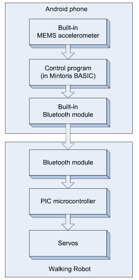
The control chain works as follows: accelerometer inputs on the phone are read by an app coded in Mintoris BASIC (which I highly recommend if you have an Android device and enjoy programming in BASIC.) The BASIC app chooses the desired gait (stopped, forwards, backwards, turn-left, turn-right, spin-left, or spin-right) based on the accelerometer inputs (essentially, which way the phone is tilted). This is translated into commands that are sent via Bluetooth to a SparkFun RN-41 Bluetooth module, commanding it to set four of its output pins high or low. This in turn commands the servo microcontroller on the robot to implement one of the seven above behaviors by sending position pulses to the robot’s eight Futaba S3003 servos. (The robot currently understands thirteen different postures and motions, but not all of these have been implemented in the phone control so far.)
The electrical design for the robot itself is fairly straightforward; here is a short description of each piece:
- Power is supplied by a 6V rechargeable NiMH battery pack (I’m using a Duracell DR10 since it was handy). This supplies the main power for the servos and the PIC microcontroller. (6V is technically out of spec for the PIC, which should only run at up to 5.5V. It seems to work well enough for now, but I do plan to regulate the PIC’s supply voltage down to 5.0 when I make a new circuit board. Separating it from the servo supply now would be tricky.) The switch at the back of the robot interrupts the main 6V power line.
- The 6V rail power from the battery is cleaned up (at least to some extent) by two large 22oouF electrolytic caps, as well as a 1uF tantalum. (Servos tend to have large swings in supply current requirements, which can cause the supply voltage to bounce around quite a bit due to the impedance of the wires and battery.)
- Power for the Bluetooth module is regulated down to 3.3V from the main 6V power rail, since the Bluetooth module is not rated for even 5V. An adjustable LM317 regulator (and associated voltage-divider resistors) is used for this. An 0.1uF tantalum cap and 0.01uF ceramic cap help clean up the 3.3V power.
- The PIC microcontroller directly feeds the eight servos that are currently implemented (the schematic below shows all 18 potential servo connections.) The servos currently implemented are LFS, LFK, RFS, RFK, LRS, LRK, RRS, and RRK. (The letters stand for {Left/Right},{Front/Rear},{Shoulder/Knee}, respectively.)
- The servos are Futaba S3003s, chosen because they’re ubiquitous and cheap. They don’t really have as much torque as I’d like, and I plan on replacing them with something a bit stronger. (This would also allow the robot to carry a larger battery pack, sensors, a WiFi module, etc.)
- The Bluetooth module is powered by the 3.3V regulator circuit, and connects directly to D0 through D3 on the PIC. Commands from the Android phone control four output lines, which select behaviors by raising or lowering D0 through D3.
- D4 through D7 are not yet implemented on the PIC, and should be tied to ground.
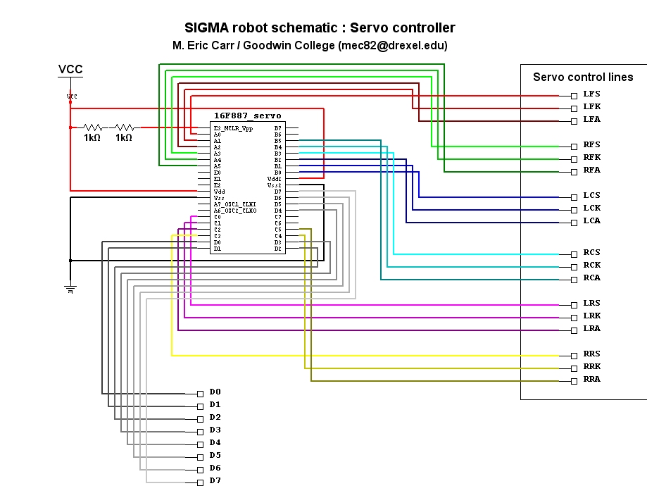
The servo controller pinout (click for larger). Only the front and rear servo sets are used, and only the shoulder and knee servos. D0 through D7 are the command-select inputs; only D0 through D3 are needed so far. These connect to PIOs 3, 4, 6, and 7, respectively, on the Bluetooth module. (PIO5 was skipped since it cannot be easily controlled.)
Here are all of the files needed to reproduce the robot, so far:
Mintoris Basic source code for phone-based controller (requires Mintoris Basic 4.0 or greater, Bluetooth connectivity, and an accelerometer. Tested on an Epic 4G running Froyo.)
Zipped PIC Assembly project for servo controller PIC (requires Microchip MPLAB, a PIC programmer such as the PICKIT2 or PICKIT3, and a PIC16F887 or similar microcontroller.)
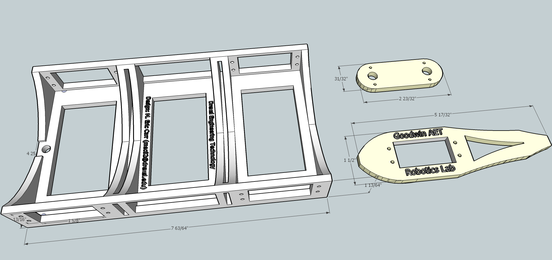
Google SketchUp 8 .skp file for robot chassis and leg pieces (requires Google SketchUp 8 or better.) One chassis and four of each leg piece is needed. I prototyped these using an STL export plugin for SketchUp, and a uPrint 3D printer (controlled with uPrint’s CatalystEX software.) The chassis is shown upside-down in the initial view (shown below); it is printed in this orientation so that it uses significantly less support material when being printed.
Still to be done:
- Improve the gait, perhaps using a Genetic Algorithm and a physics simulator;
- Implement the electronics on a single circuit board;
- Regulate the PIC supply voltage to 5V instead of the current 6V;
- Find a better / lighter battery pack;
- Implement onboard sensors and intelligent control;
- Implement a camera;
- Implement variable-speed gaits for proportional control;
- Implement automatic recharging using a docking station;
- Implement Internet connectivity via WiFi, including web-based controls.


