Amazon Dash

I’m starting to think Amazon is evil. They keep coming up with cool ways to make me spend money.

Recently, I tried Amazon Fresh — Amazon’s new grocery-delivery service. I’ve been very impressed so far: they give one-hour delivery windows, have been on-time so far with very professional service, and the convenience can’t be beat. Plus, frozen goods ship with little packets of dry ice, which is always fun to play with (as long as you’re careful to not get frostbitten.) More about that, later.

Now, Amazon has come up with Amazon Dash.

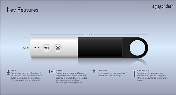
Amazon Dash. (Click for larger.)

The new Amazon Dash shopping-list gadget. (Click for larger.)

Setup involves taking the Dash out of the box, putting in the two supplied AA batteries (they even sprung for Energizers), holding down both buttons to turn it on, and running through the Dash Setup on your smartphone or tablet. (There ought to be a way to do this with a PC, too, but I’m not sure that’s supported.) All told, it took about a minute, including entering the WiFi access code into the app to finish configuration and get the Dash on the home network. They really went out of their way to make the process smooth.

Using the Dash is ridiculously easy. There are two options: Scan a UPC barcode (which works very well and is very fast), or press the microphone button to add a voice note to your list. Log in to Amazon Fresh, and the items you’ve scanned and voice notes you’ve recorded are shown and can easily be added to your shopping cart.

It’s the second-easiest way I’ve ever seen to shop, and the easiest that I’ve tried, so far. For ultimate convenience, though, there’s Amazon Dash Button. Buy one for $4.99 (and you get $4.99 credit for its use), configure it, and reordering commonly-used items (for instance, cat food or litter) is literally a single press of a button away.

Amazon Dash Button. Press this one, and detergent shows up in a day or two. Talk about convenient!

And, apparently, they’re hackable!

…although, if the Internet of Things translates into a separate button for everything, I’m gonna have to go with a Class A network and get a bigger router…

Posted in Current Events, Design, Networking, Reviews, Toys, User Interface Design | Tagged , , , | Leave a comment

Microcode

Every so often, you come across an idea that is truly brilliant. Such ideas can sometimes make complex, expensive problems seem trivial. The idea of microcode is one such idea.

In order to work its magic, the* Central Processing Unit(CPU) in a computer needs to move data around between various sub-units inside itself. Every clock cycle, a control logic circuit dictates what electronic gates must open and close to move, for example, a byte of information from the B accumulator into the adder, and then a byte from the A accumulator into the L register. The control bus and the logic behind it are the choreographers, dispatchers, and traffic cops of the CPU.

In the early days, designing a CPU involved not only deciding on the number and width of registers and choosing and implementing an instruction set, but designing and simplifying the Boolean logic required to distinguish between various opcodes, which may or may not have been numbered with regard to ease of coding.

Microcode, conceived in 1951 by Maurice Wilkes, makes all of this much easier. Instruction cycles are broken up into T-states. For each T-state of each instruction, the CPU architect decides which gates should be active and which should be off (tristated). These are collected into a matrix, which is simply implemented as a ROM array on the chip. Each bit of the ROM corresponds to the desired behavior of a particular gate (the bit number), at a particular time (T state) in a certain instruction (the opcode). There’s no need to employ complex Quine-McCluskey simplification methods — it’s just a question of connecting the ROM to the gates.


* okay, “the CPU”, or “one of the CPUs.” Sheesh.

Posted in Design, Digital | Leave a comment

Geomagnetism

Magnetic compasses work by sensing the direction of the Earth’s magnetic field. A small, magnetized piece of metal is allowed to rotate with very little friction (typically, it is balanced on a pin.) The Earth’s magnetic field then coerces the needle to point in the same direction as the field — towards magnetic North (or, equivalently, South).

Compasses normally don’t measure the magnitude of the field, however. If the Earth’s magnetic field were to double in strength but retain the same local direction, compasses would move more quickly, but would still ultimately indicate the same direction.

With a few simple additions, though, a magnetic compass can be used to deduce the strength as well as direction of the Earth’s magnetic field — at least in two dimensions.

2015-07-30 23.22.57_sm

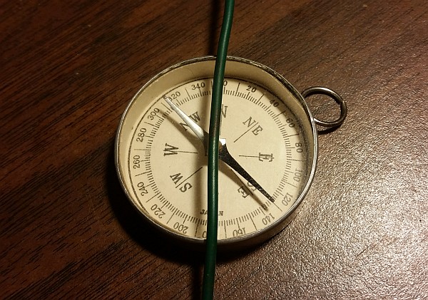
A compass, deflected from N/S by a current. (Click for larger.)

By using a coil with a carefully-controlled current flowing through it, a second magnetic field can be set up at a 90-degree angle to the natural one created by the Earth. If the current in the coil is varied until the compass needle is deflected 45 degrees from its natural position, the two fields are of equal strength (since the tangent of 45 degrees is 1.0.)

Here is the procedure to set up the experiment and calculate the strength of the Earth’s magnetic field.

  • Find a flat, open space (a table or desktop, for example) away from metal objects and furniture.
  • Place a compass on the table and align it with North.
  • Run a wire across the face of the compass, from N to S, and extended straight out as far as practical in each direction.
  • Connect the ends of the wire to a power supply, running through an ammeter
  • Starting at zero, increase the current until the needle deflects 45 degrees from N/S.
  • Note the amount of current needed to cause the 45-degree deflection

Since the needle’s direction is now halfway between the direction of the Earth’s magnetic field and the direction of the magnetic field set up by the current in the wire, the relative strengths of the two fields must be equal. (The tangent of 45 degrees is 1.)

The amount of current in the wire can be used to calculate the expected strength of the magnetic field at the distance r between the wire and the compass needle.

At 1cm, for example, you get one Gauss (100 microTesla) for every five amps of current (the relationship is linear, so such a rule of thumb is a valid specific-case simplification here.) Since the Earth’s magnetic field has a strength of about 500 milliGauss at the surface, a perpendicular magnetic field of 500 milliGauss should cause a 45 degree deflection in the needle.

So, we can do the above experiment and measure the field strength indirectly. My results so far? It seems to take somewhere between 1 and 3 amps, so the observed effect agrees to within an order of magnitude of the expected result. A narrower confidence interval will have to wait until I can find a better compass.

Then there’s the whole question of the 3D magnitude and direction of the field…

Posted in Electronics, Fundamentals, Science | Leave a comment

Your Amplitude May Vary

A signal generator is a very useful thing to have in an electronics lab. These devices can generate sine, square, and often many other waveforms, at a given amplitude and frequency. Just the thing for measuring frequency response in filter circuits — or generating a clock signal to drive a digital circuit.

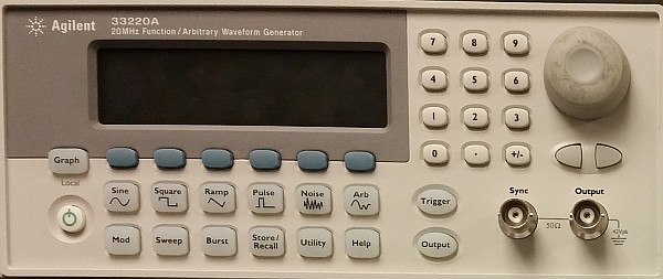
An Agilent 33220A signal generator. (Click for larger.)

However, there’s a hidden “gotcha” on many of these devices. They don’t actually measure the amplitude of the signal they put out. They rely on an internal voltage divider and calibrated amplifier stage, and assume a given load impedance — typically either 50 ohms or high-Z (effectively, an open circuit). If the load impedance matches what the signal generator has been set for, all is well, and the amplitude will be more or less correct.

If the load impedance is significantly different from the menu setting on the signal generator, though, the amplitude can be off by as much as 100%. For example, if a signal generator is set for 1.0Vpp at 50 ohm impedance, but is actually connected directly to an oscilloscope with 1Mohm input impedance, the actual output amplitude will be right about 2.0Vpp.

The moral of the story? Never trust a smiling signal generator — at least as far as impedance is concerned. Whenever you change the load impedance (which can happen by simply changing frequency, if you have a reactive component to the impedance), it’s important to actually measure the real output amplitude — for example, with a ‘scope.

Posted in Analog, Digital, Drexel, EET201, EET202, Electronics, Tools | Leave a comment