Pretty colors! (uOLED-160 review)

Recently, I found out that I had won a door prize in the 555 contest. I expected that it would be something small like a solderless breadboard or maybe a pocket DVM. Instead, I was pleasantly surprised to learn that I had won a modern, 1.7″ micro-OLED display from 4D Systems. With a MSRP of $70-something, it might have otherwise been a while before I got around to trying it out. Thanks to the generosity of Chris Savage (of Savage Circuits) in sponsoring this prize, I have the chance to experience this cool toy firsthand. (Thanks, Chris!)

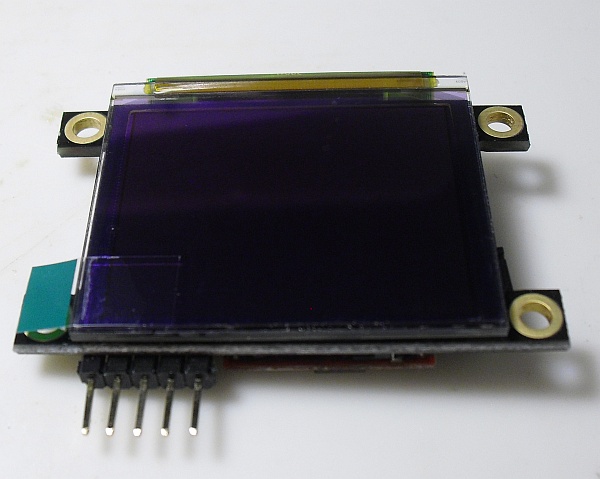
The uOLED-160-GMD1 display (click for larger)

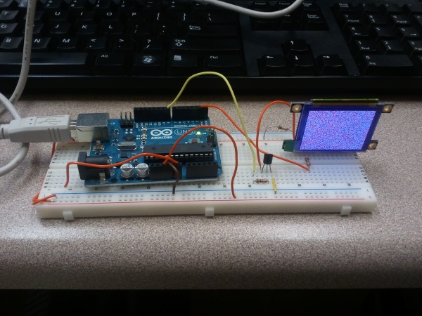
Interfacing with the display is very straightforward: supply 5VDC and ground, and connect a 1k resistor in line with the serial input, if driving it from a 5V TTL serial source. The display autodetects the baud rate up to 256k, according to the data sheet. (The Arduino I’m driving it with is known to work up to 115200 baud, so I used that.) For this application, display ground is gated via a 2N3904 transistor, allowing the Arduino to switch the display on and off (40mA is a bit too much for the Atmel to switch on its own.)

From there, it’s just a matter of sending the right commands (clear screen, set pixel, etc) to the display over the serial line. Half an hour of tinkering later (mostly because I initially didn’t read the description of the startup protocol in the instructions), I had an Arduino sketch running to display a raster scan of randomly-colored pixels.

Randomly-colored dots (click for larger)


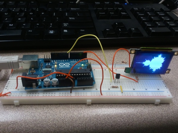
Next, I wrote my graphics “Hello, World!” stand-in: a Mandelbrot Set program. The display uses a 65,536-color scheme: five bits each for red and blue, and six for green, so I set it up for 31 iterations and used that value for Red and Blue, and twice that value for Green. This produced a distinctly red-tinted display, so I backed off on the Red value by a constant 5 (clipped to remain nonnegative), which produced a decent grayscale Mandelbrot Set image.

A Mandelbrot Set image, rendered on an Arduino (click for larger)


Reading through the datasheet, it turns out that the display supports many useful graphics primitives. So far, I’m only using clear-display and set-pixel, but the native GOLDELOX controller supports pixels, lines, polygons, circles, images, and bitblt operations, among others. It even has a slot for a microSD card.  The display draws about 40mA of current (at 5V) when running.

Overall, I’m impressed. The uOLED-160 isn’t cheap (OLEDs generally aren’t, yet), but it does provide an easy-to-use way to incorporate full-color graphics into almost any embedded system. (It wouldn’t even be too hard to drive it with a really small MCU like a PIC10F200, if need be.) The incorporated GOLDELOX daughterboard does a good job of handling the graphical heavy lifting, allowing your code to describe the display in terms of basic elements. It would make a really cool DIY programmable watch display, for one thing. (Hmm…)

Given that I got such a cool display as a freebie, there are a lot of awesome people to thank. First, Jeri Ellsworth and Chris Gammell deserve a lot of credit for coming up with the idea of the 555 contest, getting it rolling, and organizing the whole thing. They managed to attract a lot of prize sponsors while keeping the whole contest vendor-neutral — a very good idea. They also got together an all-star group of judges, including Forrest Mims (of “Engineer’s Mini-Notebook” fame) and Hans Camenzind (the inventor of the 555). Through their efforts, the contest was hugely successful, and a lot of fun!

Also, as I mentioned, this particular prize was generously sponsored by Chris Savage, who runs the blog / forum / site Savage Circuits. I actually first heard about Savage Circuits through the contest, and signed up. They have blogs, videos, and a great forum — a very cool resource for a DIYer. Since I won the door prize, Chris Savage has been in touch with me, making sure it got here OK as well as encouraging me to post a Maker Profile on the site. (Hopefully I’ll get everything together for that soon.) Thanks again, Chris!

 

Posted in Arduino, C, Coding, Components, Digital, Electronics, Toys | Tagged , , , , | Leave a comment

Puzzle cube

Like many geeks, I enjoy unique puzzles, especially when the solution is mathematically interesting. (Puzzles with nicely-defined moves / positions / candidate solutions, and which require more thought than dexterity are the best.) I have a small collection of interesting physical puzzles (which might make an interesting article someday.)

A while ago, my wife found a wooden puzzle cube.  Figuring that it was inexpensive, somewhat educational, more or less nontoxic, and might keep me from bothering her for a few hours while she studied for her Pharmacy exams, she bought it for me. (Guys never really do grow up…)

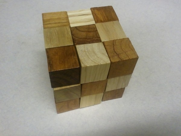
The cube in a solved state.

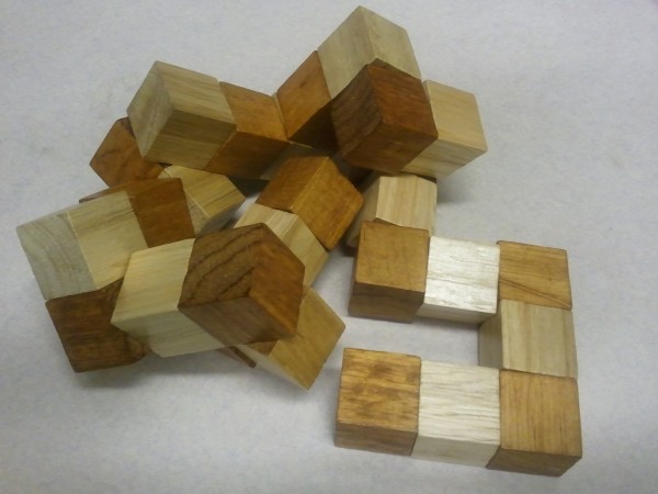
The premise is pretty simple. Twenty-seven wooden blocks are joined together by elastic thread. At sixteen points in the chain, the thread makes a right angle. When twisted into the right configuration, the blocks can be formed into a 3x3x3 cube. This is more difficult than it seems: there are some four billion possible combinations, most of which seem to be impossible, since the blocks would overlap. At least one solution must work, since the cube was initially in solved form when bought.

I played with the cube for a while, eventually solving it again, and decided it would make an interesting problem for a genetic algorithm.

The cube in an unsolved state.

Two things are needed to make a genetic algorithm (GA) work: a way to express the solution as a bitstream (or string using a fixed alphabet of characters), and a method of evaluating a candidate solution (bitstream or string).  With these two pieces, the genetic operators of crossover and mutation (with possible others added) can be repeatedly applied to a population of solutions. Artificial selection using the fitness function is used to choose the next population.

Since at each point in the cube, four directions are possible, I settled on expressing candidate solutions as strings of characters — either N, S, E, or W.  I arbitrarily chose “North” to represent “up” (positive Y direction) wherever possible and “away” (positive Z direction) when “up” was not possible. Every string of these directions would represent a valid — if not viable — candidate solution. (The distinction is central to how Genetic Algorithms work; each candidate solution, even completely randomly-generated ones, must be valid. That is, it must be a string of the right length, drawn from the acceptable alphabet — in this case, N, S, E, or W. The solution may make no sense at all — with blocks overlapping multiple times and still not fitting into the desired 3x3x3 square — but it will be able to be evaluated, since any possible solution is “gramatically” correct.)

Candidate solutions are graded on the size of the rectangular prism “bounding box” needed to contain the resulting configuration, with smaller numbers being better. (The ideal 3x3x3 nonoverlapping solution would have a fitness of 27.)  The problem of overlap was handled by penalizing solutions which overlapped — in this case, ten blocks per overlap was chosen as an arbitrary penalty.)

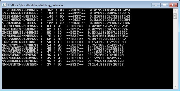
I first wrote a fitness evaluation routine, and tested it on a known-good solution. It returned the expected value of 27, so I set up a naive random-string-generator algorithm which simply tried random strings, keeping the best-so-far solution. It came up with reasonably good guesses in a short amount of time, but took 21.17 hours to come up with an optimal, fitness-27 solution: SNNESESSNWWWSEESN.

The results for a random search. After more than 21 hours, it finally found it...

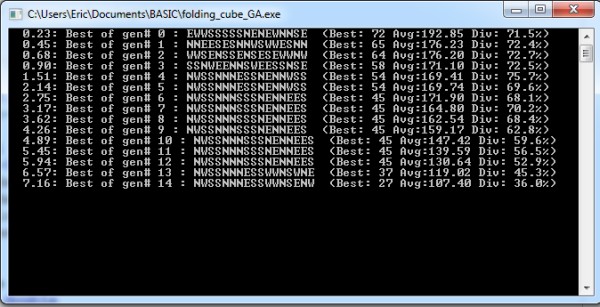
Next, I tried a genetic algorithm approach. An initial population of sequence strings was generated and evaluated. (The fitness function used was the same as before — the size of the bounding box needed to contain the result, plus ten times the number of overlapping cubes.) The fitness results were used to select individuals to be used to create the next generation. Uniform crossover and uniform random mutation were applied. It took a bit of tweaking to find optimal values (more on that later), but one GA run found a correct solution (although a different solution than the random one: SSNWSWSNNWEESEWSS) in 20.45 seconds (the 40th generation with a population size of 1000). A slightly different run found a third optimal solution — NWSSNNNESSWWNSENW — in 7.16 seconds (14 generations).

Optimal solution found in 14 generations (with population size 1,000). Only 15,000 candidate solutions (out of over four billion) were searched!

Those results represent GA runs where an optimal solution is found, so they’re a bit optimistic. Using the GA settings that I’ve come across so far, I’ve found that the GA tends to either find an optimal solution relatively quickly, or doesn’t find one within quite some time (if ever).

I’m currently working towards characterizing the effects of varying the mutation rate and fitness / selection criteria on the overall probability of the GA finding an optimal solution. For now, though, restarting randomized runs of the GA after a hundred or so generations pass without a solution seems to do the trick; a solution is usually found sometime in the first five or ten minutes — still a speedup of over a hundred times compared to the blind random search procedure.

Myth confirmed: Darwinian evolution does work — at least in silico.


Posted in BASIC, Coding, Math, Science | Tagged , , , , , | Leave a comment

Full of hot air

There is a definite trend in electronics away from the older, larger through-hole components in favor of smaller, denser (and often more complex) surface-mount components. For now, many microcontrollers and support chips are available in through-hole DIP form, suitable for breadboarding or soldering using through-hole PC boards.

The writing is on the wall, though: to work with smaller components and/or more complex components with higher pin count, surface-mount techniques and equipment are needed. For one thing, FPGAs are difficult or impossible to find in DIP form factor; the only options are to use dev boards for everything (expensive and unwieldy for finished products) or to be able to work with QFN and other surface-mount packages.

I had recently come across an old parallel-port scanner being given away at a yard sale, and picked it up. My wife thought I was crazy — but scanners need stepper motors to work, and stepper motors are useful to have and normally cost actual money. I figured if nothing else, I could always just take out the stepper and throw away the rest. I hate to see technology go to waste, though, so I resolved to salvage whatever I could from the scanner. I got the stepper motor, a few gears, a lens assembly, a cold cathode light tube and its easy-to-use high voltage supply — but the rest of the components were mostly surface mount.

I’d been thinking of getting a hot-air rework station for a while, and this made the decision for me. So many devices are thrown away or sold for next to nothing at thrift stores and flea markets. Rather than seeing these components go into the Dumpster, why not build a stock of SMT components and teach myself surface-mount techniques at the same time? I ordered a nice-but-not-too-expensive Aoyue 852A++ rework station with a vacuum pick-up tool, and set the circuit boards from the scanner aside.

Last week, the rework station arrived. I tried it out at work (we’re seriously considering getting one for a device we’re developing). Here is a video showing how relatively easy it is for a hot-air-rework newbie to recover small components (most likely logic drivers and a couple of capacitors) from a board…

Now for the next steps: classifying and reusing the recovered components in new circuits!

Posted in Electronics, Tools | Tagged , , , , | Comments Off on Full of hot air

BINAC

While walking home one day, I took a small detour to check out an interesting-looking Geocache. When I arrived at the coordinates, I found a historical marker:


BINAC -- possibly the world's first true computer -- was built here! (Click for larger.)

BINAC, the world’s first “commercial, electronic, stored-program, digital computer” was built and tested here in North Philadelphia. (Its inventors, Presper Eckert and John Mauchly, were also the creators of ENIAC, at the nearby University of Pennsylvania.)

That’s a lot of qualifiers for a historical marker, but nearly everything that would even remotely be called a “computer” these days is an “electronic, digital, stored-program computer.” The vast majority of them also happen to be commercial. In a real sense, BINAC was one of the first “real” computers — and probably the first one that really started to resemble the core architecture of modern computers.


Posted in Digital, Nostalgia | Leave a comment