Breadboard oscilloscope

Miniaturization has made a lot of cool electronic toys tools possible. Often, when the size and cost of a device is greatly reduced, it opens up many new possibilities. In-the-field tests that would be impossible with a rackmount or desktop tool and awkward with a handheld one suddenly become easy when the tool can be almost built in to a project under development.

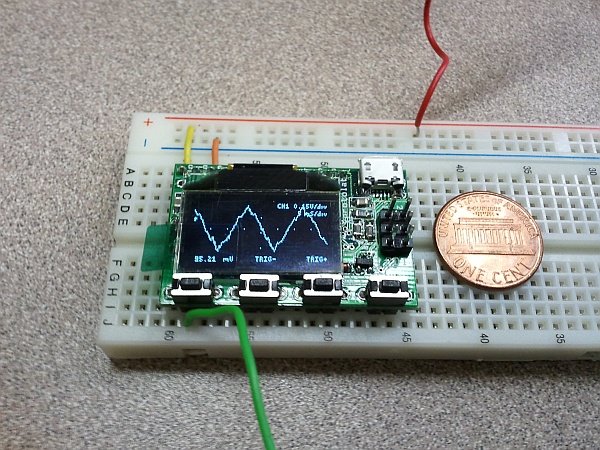
One great example of this is the Gabotronics XProtoLab. It’s a miniature, breadboardable dual-trace digital oscilloscope! While it doesn’t have all of the functionality of a desktop ‘scope (notably, its 2MSPS sampling rate limits it to low frequency signals), the ability to stick it on a breadboard or dev board and view signals in the field can be very helpful.

The Gabotronics XProtoLab breadboardable oscilloscope. (Click for larger.)

Setup and use is very straightforward: provide 5VDC and ground, and connect the signals to be monitored. The four control buttons operate various menu options, allowing the time and voltage scales to be set, as well as other functions (triggering type and level, persistence, etc) to be controlled.

The cost is actually another plus — at $49US, it’s cost-effective to have one or two of these on hand for measurement of signals in the field. GPS-enabled projects, for example, don’t do well indoors, and debugging often involves monitoring system functionality while moving. In an industry where a blinking LED is a time-honored diagnostic tool, the advent of low-cost, affordable tools like this is very welcome.


Posted in Analog, Digital, Electronics, Tools, Toys | Tagged , , , , , , , | Leave a comment

RIP, Dennis Ritchie

I recently learned that Dennis Ritchie (of “Kernighan and Ritchie” fame) passed away a few days ago. He will be very much missed by the technical community. How many people can say that they were the principal designer of (and co-wrote THE book on) C — the single most influential computer language ever written?

If you Google “C programming language,” the top result is the Wikipedia description of the language itself. Just under that is the Wikipedia article on the book of the same title. Those of us in the industry refer to it as “Kernighan and Ritchie,” “The Book,” “K&R,” “The Bible,” and “The Book of C.” It’s a small, unassuming book — but very well-written. It provides a solid yet approachable introduction to programming in C. (It’s also responsible for the “Hello, World!” programming meme, started in a Bell company memo by Ritchie’s co-author Brian Kernighan.) If I had to cut my library down to only the books I could fit in my backpack, my copy of K&R would be included, no question about it.

C is almost literally everywhere. Microcontrollers with firmware written in C run our cars, make our coffee, and guide us to our destinations. More powerful CPUs running programs written in C are used in our computers and smartphones. The Linux kernel is written largely in C, and Windows and Mac OS also no doubt contain at least significant amounts of C code. Android programs may be written in (C-based) Java, but the underlying OS is written in C. The computer I’m using to type these words is running a browser (Chrome) no doubt written in a C-like language. The webserver which hosts this site runs the “LAMP stack“: Linux (written in C); the Apache webserver (written in C); MySQL (written in C and C++); and PHP (written in C). The routers shepherding the packets containing this text use firmware that is almost certainly written in C.

Although C was written between 1969 and 1973 as an operating-system language, it is still very much in widespread use today, and has inspired and influenced many other languages. Programs written in C++, C#, Java, Perl, PHP, Go, and others all owe their basic syntax and structure to C.

C is still widely used after so many years because it manages to be most things to most people. It is a very fast, efficient compiled language (nearly as fast as hand-written assembly code, in most cases), yet is far easier to learn and use than assembly. It can be used to write complex, multithreaded operating systems, create virtual 3D game worlds, or to write simple programs to make 40-cent microcontrollers blink an LED or run a toaster.

RIP, Mr. Ritchie. Thanks for giving the world one of the solid cornerstones of the Information Age.


Posted in C, Coding, Current Events, Digital, Digital Citizenship | Tagged , , , , , | Leave a comment

Unintentional Destructive Testing

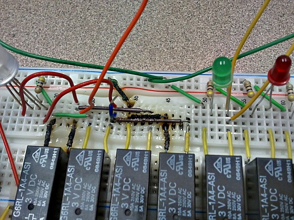
Note to self: Current handled by circuits on solderless breadboards should be limited to no more than 1A or so. Otherwise, things start to get smokier than normal, as demonstrated by what a prototype control board did to itself during a test run…

High current = high temperatures = bad. (Click for larger.)

This kind of failure, though, demonstrates a valid diagnostic technique (albeit one taken to destructive extremes in this case): All else being equal, a conductor will become warmer when carrying more current. For example, it’s evident from the above picture what the high-current path was — through the first and fourth relays, which make up one half of an H-bridge setup. For some reason, the final part of the path — the short green wire at the upper left — didn’t get cooked, although it was carrying just as much current as the rest of the circuit. A different formulation of plastic, perhaps…?

Given an IR thermometer, this resistive heating effect (hopefully with less extreme temperatures) can be used to determine which chips are dissipating more power than others in a circuit. It can also sometimes be used to determine which device is causing a short — without risking burning your fingertips. Simple IR thermometers are available for around $20US; I picked one up a while back and keep finding new uses for it.


Posted in Drexel, Electronics, Power | Tagged , , , , | 2 Comments

TIL311 replacement

Back in the day, when men were men and computers were programmed in hexadecimal, Texas Instruments produced a nifty little display chip called a TIL311. This chip took a 4-bit nibble as input, and produced a single hex digit on a built-in LED display. As if that weren’t cool enough, TI packaged it in translucent red; you could almost convince yourself that you saw the electrons moving through the traces as the display digits changed. This wasn’t a consumer-oriented BCD display for use in calculators and clock radios (though it would work nicely for that) — this was an actual hexadecimal display, capable of displaying numbers beyond zero-through-nine.

To paraphrase This Is Spinal Tap, “these went to fifteen!”
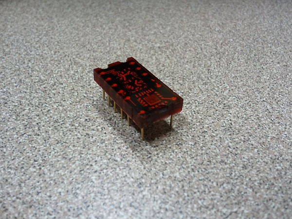
A TIL311 hex decoder and display (click for larger)
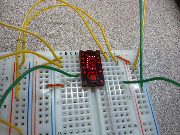
 

A TIL311 displaying hex digit "C": 1100, or decimal twelve. (Click for larger)


Unfortunately, although they’re still as useful as ever, TIL311s are extremely scarce today. The best price I could find online was $19.95 apiece. (For comparison, you could get several backlit 32-character LCD displays for the same cost.)

For Drexel’s EET325 Microprocessors class this term, we wanted to capture the essence of programming a vintage 8-bit CPU like the Z80. A modern LCD display would be simpler to implement, but somehow it just wouldn’t be the same. Hex displays like the TIL311 worked beautifully: one hex digit exactly covers four bits. Two digits cover one byte (for the data bus) and four cover a 16-bit word (for the full address bus on the Z80). The most recent versions of the DrACo/Z80 are true 8-bit machines, though: the address bus is 8 bits wide (although expandable to 16). Because of this, only four hex digits are needed; two for the address and two for the data.

Even so, four TIL311s per board would add $80 to the bill of materials — roughly doubling the cost. This, we figured, was an opportunity to put our LPKF PCB plotter to use creating some modern TIL311 replacements. A PIC16F1825 microcontroller, a common-anode seven-segment LED display, and seven resistors take the place of TI’s slick one-chip solution. It isn’t nearly as pretty, but it gets the job done for a bit less money.
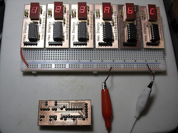
The displays in action, and a view of the single-layer traces. (Click for larger.)

A few design revisions and squashed bugs later, the first of the new boards are up and running. The PIC runs in a continuous loop, monitoring the four data pins and updating the seven-segment output based on data in a lookup table. (The code is easily converted to a common-cathode design by inverting the display bits; the board would have to be modified to support this. It would have been nice to be able to do this in software by using an I/O pin as a switchable common, but unfortunately there were no spare pins left.)

Here is the zipped PIC project to reproduce this display for yourself, along with the layout file used to create the board layout in FreePCB. The design is completely single-layer for ease of soldering, although if using double-sided copper-clad boards like we did, the holes on the top layer must be insulated. The PIC actually runs at its slowest self-clocked speed of about 31kHz; since the monitor-lookup-and-update loop only takes 36 cycles, the display can still be updated at several hundred Hz — fast enough to be a blur if the Z80 is running that fast. (The design should work at any speed, since no timing at all is used; the PIC is simply emulating combinatorial logic as fast as possible/necessary.)

Some details on construction: All resistors are 470 ohm, although any similar value should work OK. The connector is a standard 0.1″ row connector, with the plastic insulator pressed all the way to one side. This way, the connector can be inserted through the top of the board, soldered to the bottom side like all of the other components, and have enough pin length left to comfortably fit into a solderless breadboard. Since these boards will be used in a classroom lab setting, I opted to socket the PIC. That way, if one accidentally gets its power reversed and/or is introduced to 12V instead of 5V, we can easily replace it.

Since the LED display is driven by the PIC, it is less likely to be damaged due to incorrect connections; the PIC is unlikely to pass enough current to it to cause damage. The LED is keyed, and will only go in one way. (Yes, it’s supposed to be upside-down; these boards don’t use the decimal point, and the circuit layout worked much better that way.)

I’m still working on refining the parameters for producing boards on the LPKF plotter (not to mention dealing with some persistent alignment issues) — but it’s definitely getting there.

If you decide to make one of these for yourself and have questions, please email me (“Eric” at this domain); I’ll be happy to help.

 

Posted in Assembly, Coding, Components, Digital, DrACo/Z80, Drexel, EET325, Electronics, Level 3, Nostalgia, PIC Microcontrollers, Projects | Tagged , , , , , | 5 Comments