Voltage dividers

One of the fundamental building blocks of electronics circuits is the voltage divider. By combining two impedances in series, a voltage can be obtained in between these two elements that is some (possibly complex) fraction of the original voltage.

For DC circuits, voltage dividers simply involve two or more resistances — and the math is straightforward:   Vx = Vt * (Rx / Rt), where:

  • Vx is the resulting voltage across one or more elements of the divider;
  • Vt is the total supply voltage across the voltage divider;
  • Rx is the impedance (for DC circuits, the resistance) between the output points; and
  • Rt is the total impedance (for DC, resistance) of all elements of the divider.

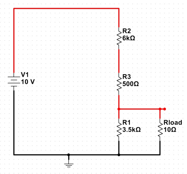
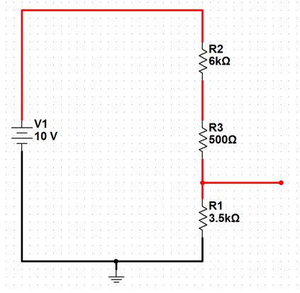
As an example, here is a schematic of a basic voltage divider set to produce 3.5V output from a 10V source:

A voltage divider designed to produce 3.5V output, from 10V.

The above formula works well, if there is no significant load on the voltage divider. If the only thing connected to the output was a voltmeter, the output voltage would be very close to 3.5V. If, however, a significant load were attached (say, a light bulb with a 10-ohm resistance), the situation would be quite different…

A "loaded" voltage divider. (Click for larger.)

The voltage divider equation from above is still valid, but the new load resistor must be taken into account. With Rload in parallel with R1, the equivalent resistance of the two can be calculated with the parallel resistor formula: 1/Rt = (1/R1 + 1/Rload). The resulting resistance for the combination is about 9.972 ohms. (R1 hardly matters at all, at this point.)

Substituting this equivalent resistance in creates a very different-looking voltage divider…
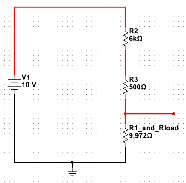
The loaded voltage divider, with the R1/Rload combination replaced by its equivalent. (Click for larger.)

Calculating the new, loaded output voltage shows what a difference a low-resistance load makes: Vx = Vt * (Rx/Rt) = 10*(9.972/6509.972) = 0.01532V, or about 15mV.

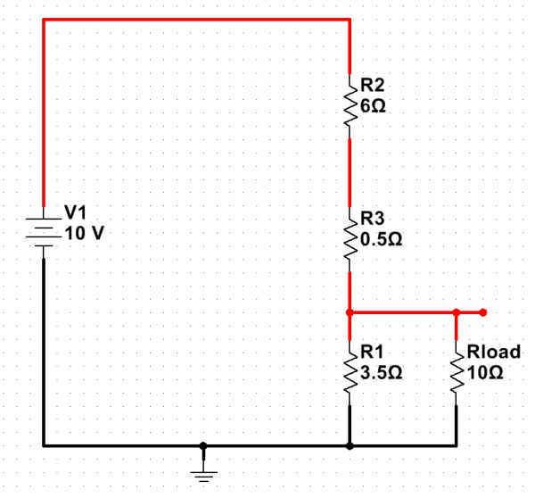
This dramatic voltage drop occurs because the load resistance is so small in comparison to the resistances used in the voltage divider. One possible solution for this is to use smaller value resistors in the divider, making things more equal:

A "stiff" voltage divider -- using much lower resistances. (Click for larger.)

This helps with the voltage-drop problem somewhat:
Vx = Vt * (Rx/Rt) = 10 * ( 2.593 / 9.093) = 2.85V

There’s a big price to pay for this, though! Even without the load resistor, there is now 1A of current through the voltage divider — at all times. At a supply voltage of 10V, this means that the voltage divider will be dissipating 10 watts even while not powering a load — not exactly energy-efficient. For this reason, voltage dividers are usually used to provide reference voltages for solid-state regulators, instead of being used to actually reduce the main power voltage directly.

 

Posted in EET201, Electronics, Fundamentals | Leave a comment

Celsius Intuition

For reasons that I’ve mentioned before, I prefer to use SI units whenever possible. For me, it’s about practicality — using SI units makes the math easier, since unit conversion requires few or no “magic numbers” to convert from one unit to another.

Having grown up in the U.S., though, developing an intuition for SI units is not always easy. After several decades of exposure to U.S. traditional units, it’s difficult to not think of a nice cool day as “68 degrees” instead of “20 degrees Celsius.”

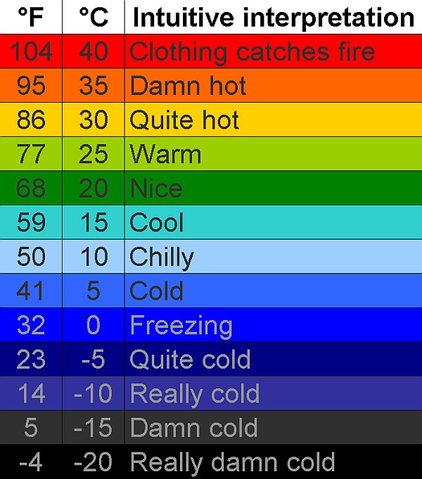
After Plan A (setting the weather widget on my phone to use Celsius) simply resulted in my not being sure what to wear, at least without mentally converting the reported temperatures back into Fahrenheit, I decided to make up Plan B: a chart, specifically designed as a “Remedial SI” tool to help me and fellow unit-anachronistic residents of the U.S. develop an intuitive understanding of degrees C.

Enjoy.

A chart to convert degrees Celsius into intuitive meanings. (Click for larger.)
Posted in Math, Science | Leave a comment

Ugly hack of the week

Forgive me, fellow Digital Design geeks, for I have sinned. Faced with a lack of 74LS245 tristate buffer ICs (I swear they were in the cabinet last week), I have created a truly ugly hack.

The latest iteration of the 8-bit DrACo/Z80 design uses a PIC16F688 as a custom 8-bit up/down counter, to run the address lines. This should make it quite a bit easier to program than previous designs, while not making the design any more complex. The data bus is now run straight from the logic switches on the CADET II trainer into a single 74LS245 tristate buffer chip. When writing to the data bus manually, the ‘245 is enabled and the eight bits from the switches are copied onto the data bus. Otherwise, the ‘245 is disabled (tristated), allowing the Cypress memory chip or the Z80 to control the data bus. We’ve been using this design for three or four years now, and it works nicely.

The lack of available ‘245s, though, meant that the logic switches would be continually driving the bus, contending with the output from the memory chip if it were enabled for a read. Bus contention is a Bad Thing™ — because it not only causes chaotic computer behavior, but can actually damage components due to two low-impedance sources driving the same net. The ‘245 prevents this, since it is set to only enable its outputs when nothing else is driving the data bus. Without it, the system will work incorrectly and could possibly burn itself out.

The solution ugly hack workaround was to connect the switches to the data bus via 470-ohm resistors. (I would have used 1ks, but there weren’t as many of those handy.) When the switches are the only thing driving the bus, they should still have low enough impedance to assert the correct values onto the data bus. When the memory is driving the data bus (during a read), its low-impedance output (20mA) should be enough to overcome any resistors pulling in the opposing direction.

It should work for now, but it’s definitely ugly.


Posted in Digital, DrACo/Z80, Drexel, Hacks | Leave a comment

Earth Hour

Technological innovation is great, but it’s also important to think of the Earth. Our consumption of nonrenewable resources is endangering the environment.

Earth Hour, scheduled for 8:30PM-9:30PM tonight (local time, in each time zone) is an attempt to increase our awareness of our power consumption. Often, lights are on that don’t need to be; HVAC systems are left running while the windows are open, and energy is wasted in many other ways.

Turn the lights out for the Earth for an hour — but more importantly, think about ways we can do more, instead of just using more.


Posted in Current Events, Digital Citizenship | Leave a comment