Components: LEDs

Just about every electronic device produced in the past twenty years or so uses one or more light-emitting diodes (LEDs). They are typically used as indicators (for power status, low-battery warnings, caps lock and number lock on keyboards, etc), but are also sometimes used to provide lighting (display backlights, “flash” lighting on digital cameras, as flashlights, etc.)

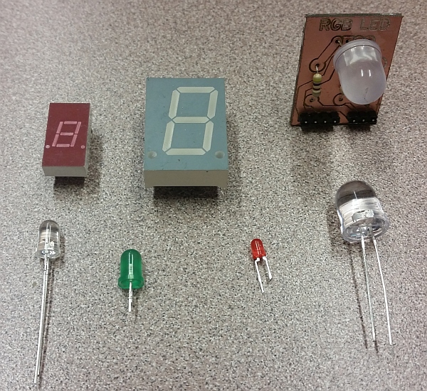
An assortment of LED types.

An assortment of LED types. (Click for larger)

LEDs, in terms of light produced per watt consumed, are many times more efficient than incandescent light bulbs. They generate almost no heat, so nearly all of the power they consume goes directly into producing light. Because of this and other factors (for one thing, they’re extremely reliable when properly used), they have increasingly been used as replacements for incandescent light bulbs for indication and illumination.

If you look closely at modern traffic lights, you might notice that they are made up of a collection of dots, rather than a single glass lens. In place of a light bulb drawing hundreds of watts, a couple dozen LEDs do the same job while using far less power and requiring far less maintenance. Brake lights and tail lights on cars are also good candidates for LEDs, since reliability is important for those applications.

LEDs are also relatively inexpensive: a red or green indicator LED typically costs just a few cents when purchased in bulk. More exotic LEDs can cost a few dollars or more — with the price increasing greatly as the power increases (there’s still not a huge market for really high power LEDs, and they’re somewhat tricky to manufacture, so the economy of scale isn’t quite there yet.)

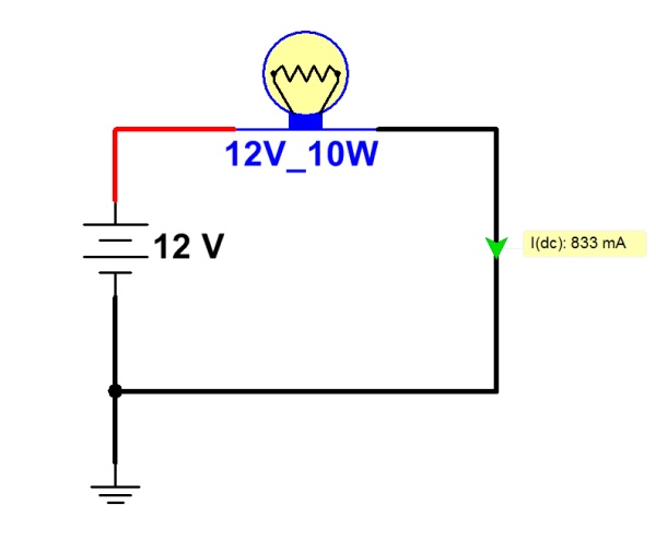
Using LEDs in a circuit is somewhat trickier than simply using a light bulb — although not much. A light bulb is basically just a low-value resistor whose resistive element gets hot enough to glow. They are, to some extent, self-regulating: a light bulb’s resistance increases as it gets hotter, limiting current flow through it somewhat. Given a light bulb of the proper voltage rating, it can simply be connected across the terminals of a battery or power supply.

An incandescent lamp circuit

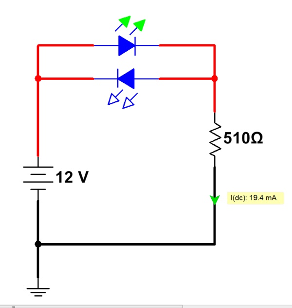
LEDs, on the other hand, require a bit more finesse. First of all, they are diodes — which means that they only allow a significant amount of current to pass in one direction. The cathode of the diode (typically, the shorter lead on the LED package) must be connected to the negative side of the power source. Otherwise, no current will flow.

The forward-biased LED conducts current; the reversed-biased one doesn’t.

In addition, diodes (including LEDs) always have a characteristic “voltage drop.” A simple way of understanding this is that the diode will “try” to limit the difference in voltage across its terminals to no more than this “voltage drop.” It does this by lowering its effective resistance as the amount of current increases (see “Ohm’s Law”), so that the voltage drop remains nearly constant.

The problem is that too much current will burn out the diode. If an LED were connected across a pair of C-cell flashlight batteries (which produce roughly 3V in series), the voltage would be significantly more than the LED “wants” to see. It would lower its resistance until the voltage drop across the LED matched this built-in limit. By this time, the current flow would be so high that the LED would get very hot and quickly burn out with a brightly-colored flash. (If you’re lucky, you might even get to see the Magic Blue Smoke escaping. Once the Magic Blue Smoke is gone, the component is ruined.)
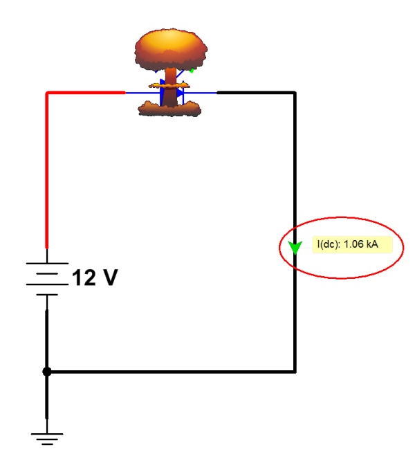
Without a current-limiting resistor, the LED will allow too much current to pass, and will be destroyed.

The solution to this is to put a resistor (typically 470 ohms) in series with the LED. This gives the rest of the voltage drop somewhere to go, and limits the current in the circuit to a value the LED can handle (typically 20mA or so, for a standard 5mm LED.) With the addition of a resistor (about 1 cent, in bulk) an LED can make a good, easy-to-use indicator for a circuit.

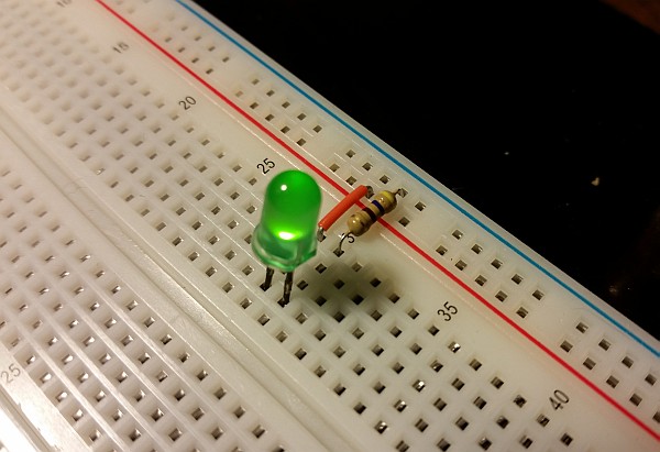
An LED on a breadboard, with a 470-ohm current-limiting resistor. (Click for larger.)

To calculate the correct size of the resistor, check the LED data sheet for the correct current that should flow through the LED. Then find the typical voltage-drop value from the datasheet (usually larger for blue and white LEDs; smaller for red LEDs). With these two values (voltage drop and current), you can calculate the correct series resistor as follows:

R = (V_t - V_led) / I_led

This calculation works by determining what the voltage drop should be across the resistor (that is, the total voltage minus the LED’s voltage drop per the datasheet.) This is divided by the current that should flow through the LED, to give the required resistance. (Remember Ohm’s Law?)

When connecting more than one LED (such as in a seven-segment numeric LED display), it’s best to provide a separate resistor for each LED. That way, the brightness of the LEDs remains constant regardless of how many LEDs are lit at one time. With all LEDs sharing a single current-limiting resistor, LED brightness will decrease if more than one is lit at a time.

Posted in Building blocks, Components, Electronics, Fundamentals, HOW-TO | Tagged , , , , , , , , , | Leave a comment

Using a 16×2 LCD display

One of the most popular standard peripherals for microcontroller projects is the ubiquitous 16×2 text LCD display. These displays are useful for the display of information generated by a device (temperatures, voltages, statuses etc.) In addition, they can make debugging a lot easier, by providing a play-by-play description of what is going on.

[16x2 LCD display]

A typical 16×2 text LCD display. (Image courtesy of Wikipedia.)

Here is a description of how to connect and use these displays, for PIC and similar microcontrollers. (PIC code is provided as an example.)

8-bit mode is described here. Most of these displays can also run in 4-bit mode if needed, which can save four GPIO pins.

If you’re using an Arduino, the instructions are slightly different (and also slightly easier): check out the Arduino LiquidCrystal tutorial for directions.

Hardware connection:

A standard parallel 16×2 LCD has a sixteen-pin interface. Numbered from 1 to 16, these typically are:

  • Ground
  • Vcc (typically 5V, but sometimes 3.3V)
  • Contrast
  • R/S
  • R/W
  • E
  • D0 through D7
  • Backlight anode
  • Backlight cathode

Ground and Vcc are connected as you would expect. Contrast is connected to a 10k potentiometer between Ground and Vcc. Connect R/S, R/W, and E to three GPIO pins on your microcontroller. Connect D0 through D7 to the corresponding pins on a single-byte port if using a PIC or similar microcontroller (I typically use PORTD on a PIC16F887).  If you’re short one pin, R/W can generally just be grounded instead of being connected to the microcontroller. (Most LCD functions don’t rely on reading data back from the LCD.)


LCD_sm

Control and data bytes are sent to the display, one byte at a time, by strobing the E line low. If the R/S line is low, the bytes are interpreted as control codes. If R/S is high, the bytes are interpreted as data to be displayed (in ASCII).

To set up the display, a sequence of control codes should be sent. There are various (minimum) delay requirements after each control code. Here is the sequence to get the display up and running:

  • Set R/S low
  • Start off with E high
  • Send a byte of 0x38:
    • Place 0x38 on the data bus (D0 through D7)
    • Strobe E low for 1ms (conservative, but works)
    • Wait 200ms
  • In the same way, send the following bytes in this order:
    • 0x0C
    • 0x01
    • 0x06
    • 0x02
  • Raise the R/S pin to go into data mode
  • Send the data to be displayed as ASCII bytes, one byte at a time.

Here is an LCD driver library, written in assembly for 8-bit PIC microcontrollers. It relies on delay routines from a delay library that I wrote. Both may be freely re-used for noncommercial purposes, as long as attribution information is kept. (CC BY-NC-SA).


Posted in Arduino, Building blocks, Digital, Electronics, HOW-TO, PIC Microcontrollers | Tagged , , , , , , , , , | Leave a comment

Dumpster Divin’

Several months ago, SparkFun came up with the idea of a “Dumpster Dive,” where they would sell mystery boxes full of random stuff they were trying to get rid of — old discontinued stock, scuff-and-dent sale items, and so on.

A SparkFun Dumpster Dive box

A SparkFun Dumpster Dive box

The first batch sold out very quickly, though, and although I was able to submit an order, they ran out of stock before it could be fulfilled. I was disappointed, but they did throw in a $10 gift code as an apology. Fortunately, due to how insanely popular the initial Dumpster Dive event was, they decided to do it again last month.

This time, I was ready. I was logged in, had my payment options updated, and had a few other small items in my cart. When the page went live, I grabbed one and checked out within about thirty seconds. A week or so later, it arrived.

The Box Has Arrived!

The Box Has Arrived!

Unboxing

So, what was in the box?

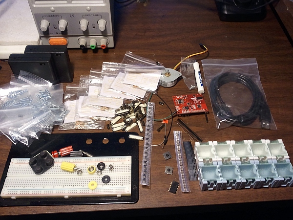
The contents of the Dumpster Dive box.

The contents of the Dumpster Dive box. (Click for larger.)

Here’s what I found (roughly, from left to right):

  • Two battery-holder boxes with switches, which hold 4 AA batteries each;
  • A mountain of small machine screws;
  • Several bags of 330-ohm resistors;
  • A bunch of jumper-pin connection terminals;
  • A bunch of SMD ribbon connectors (for touchscreen displays etc);
  • A breadboard (Some Assembly Required™);
  • A strip of surface-mount capacitors (at least I think they’re caps);
  • Two small assemblies which look like analog trackstick sensors;
  • A diode;
  • A small strip of unidentified surface-mount parts (two-terminal);
  • Some pin connectors;
  • Some SMD buck converter chips;
  • Two jumper wires;
  • A 6DOF sensor board with a few bent/missing pins (nothing too bad);
  • A bipolar stepper motor;
  • Two small screws;
  • A mini USB cable; and
  • Ten small interlocking storage boxes.

Not too bad for ten bucks plus shipping!

Posted in Electronics, Reviews, Toys | Tagged , , , , , | Leave a comment

Data Sheet Lookup

It can often be difficult to find reliable datasheets for various electronic components. It’s one thing to use a resistor or capacitor without a datasheet — most of the relevant specs can be measured or at least estimated. When working with more complex devices such as microcontrollers or digital sensors, though, a datasheet is usually essential.

I recently came across a very useful datasheet search engine site — datasheets360.com. They claim to have over 100 million parts with datasheets indexed, and are planning to eventually have over 350 million total.

I tried several random parts and was able to find the correct data sheets for each of them…

For some parts, they list prices from many of the usual suspects: Mouser, Digikey, etc. (For some reason, no vendors were listed for the EPROM. Perhaps their time portal to the early 1980s is still under construction.)

I’ve added their search widget to the right-hand menu. Check it out.

Posted in Analog, Design, Digital, Resources | Leave a comment