Geomagnetism

Magnetic compasses work by sensing the direction of the Earth’s magnetic field. A small, magnetized piece of metal is allowed to rotate with very little friction (typically, it is balanced on a pin.) The Earth’s magnetic field then coerces the needle to point in the same direction as the field — towards magnetic North (or, equivalently, South).

Compasses normally don’t measure the magnitude of the field, however. If the Earth’s magnetic field were to double in strength but retain the same local direction, compasses would move more quickly, but would still ultimately indicate the same direction.

With a few simple additions, though, a magnetic compass can be used to deduce the strength as well as direction of the Earth’s magnetic field — at least in two dimensions.

2015-07-30 23.22.57_sm

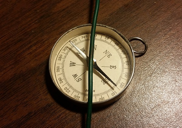
A compass, deflected from N/S by a current. (Click for larger.)

By using a coil with a carefully-controlled current flowing through it, a second magnetic field can be set up at a 90-degree angle to the natural one created by the Earth. If the current in the coil is varied until the compass needle is deflected 45 degrees from its natural position, the two fields are of equal strength (since the tangent of 45 degrees is 1.0.)

Here is the procedure to set up the experiment and calculate the strength of the Earth’s magnetic field.

  • Find a flat, open space (a table or desktop, for example) away from metal objects and furniture.
  • Place a compass on the table and align it with North.
  • Run a wire across the face of the compass, from N to S, and extended straight out as far as practical in each direction.
  • Connect the ends of the wire to a power supply, running through an ammeter
  • Starting at zero, increase the current until the needle deflects 45 degrees from N/S.
  • Note the amount of current needed to cause the 45-degree deflection

Since the needle’s direction is now halfway between the direction of the Earth’s magnetic field and the direction of the magnetic field set up by the current in the wire, the relative strengths of the two fields must be equal. (The tangent of 45 degrees is 1.)

The amount of current in the wire can be used to calculate the expected strength of the magnetic field at the distance r between the wire and the compass needle.

At 1cm, for example, you get one Gauss (100 microTesla) for every five amps of current (the relationship is linear, so such a rule of thumb is a valid specific-case simplification here.) Since the Earth’s magnetic field has a strength of about 500 milliGauss at the surface, a perpendicular magnetic field of 500 milliGauss should cause a 45 degree deflection in the needle.

So, we can do the above experiment and measure the field strength indirectly. My results so far? It seems to take somewhere between 1 and 3 amps, so the observed effect agrees to within an order of magnitude of the expected result. A narrower confidence interval will have to wait until I can find a better compass.

Then there’s the whole question of the 3D magnitude and direction of the field…

Posted in Electronics, Fundamentals, Science | Leave a comment

Your Amplitude May Vary

A signal generator is a very useful thing to have in an electronics lab. These devices can generate sine, square, and often many other waveforms, at a given amplitude and frequency. Just the thing for measuring frequency response in filter circuits — or generating a clock signal to drive a digital circuit.

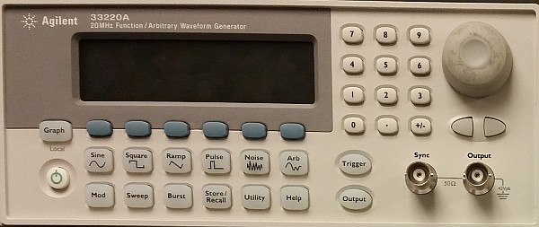
An Agilent 33220A signal generator. (Click for larger.)

However, there’s a hidden “gotcha” on many of these devices. They don’t actually measure the amplitude of the signal they put out. They rely on an internal voltage divider and calibrated amplifier stage, and assume a given load impedance — typically either 50 ohms or high-Z (effectively, an open circuit). If the load impedance matches what the signal generator has been set for, all is well, and the amplitude will be more or less correct.

If the load impedance is significantly different from the menu setting on the signal generator, though, the amplitude can be off by as much as 100%. For example, if a signal generator is set for 1.0Vpp at 50 ohm impedance, but is actually connected directly to an oscilloscope with 1Mohm input impedance, the actual output amplitude will be right about 2.0Vpp.

The moral of the story? Never trust a smiling signal generator — at least as far as impedance is concerned. Whenever you change the load impedance (which can happen by simply changing frequency, if you have a reactive component to the impedance), it’s important to actually measure the real output amplitude — for example, with a ‘scope.

Posted in Analog, Digital, Drexel, EET201, EET202, Electronics, Tools | Leave a comment

Granddad’s Altimeter

One of the most interesting mementos that I have from my grandfather is a surplus mechanical altimeter from the early days of United Airlines. It was an unusual object for a kid to see on someone’s bookshelf — even given that Granddad was a maintenance supervisor for United. I would look at it and wonder what it was and why it was there — until one day I asked him about it.

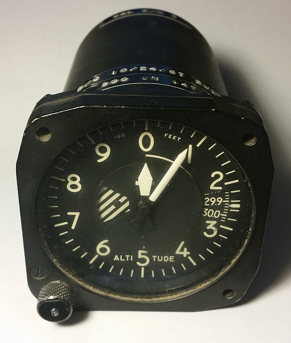
Granddad's altimeter / barometer. (Click for larger.)

Granddad’s altimeter / barometer. (Click for larger.)

He told me that it was an aircraft altimeter — and that it still worked well, although it hadn’t been calibrated in a long time. Pressure altimeters, such as this one, work by comparing the ambient air pressure to the current theoretical sea level air pressure for a given location (measured by weather stations at airports.) Since air pressure decreases with altitude (at sea level, by about one inch of mercury for every 1000 feet), the difference in air pressure can be used to determine an aircraft’s current pressure altitude. When corrected for local weather-related changes in air pressure, a reasonably good estimate of the aircraft’s actual MSL altitude can be obtained.

Granddad, as it turned out, was using the altimeter somewhat backwards — as a barometer. Since the altitude where he lived was nearly at sea level, he could set the altimeter’s barometric setting to the standard value of 29.92, and then use it to monitor changes in the local air pressure. If it showed zero altitude — sea level — the local air pressure must be 29.92 inches of mercury. If it read lower, that meant that the air pressure was higher than average, and fair weather could be expected. When it started reading higher than sea level, the air pressure was lower than average, possibly indicating stormy weather.

I found that to be one of many valuable lessons that Granddad taught me over the years I knew him: Just because something wasn’t intended to do something, doesn’t mean it can’t do a perfectly good job.

Besides, it looks a lot cooler than a typical barometer — and makes such a cool, practical,
conversation piece.

Posted in Aviation, Nostalgia, Science | Leave a comment

Ladyada interviews Paul Horowitz

Now here are two celebrities actually worth watching. Limor “Ladyada” Fried, electronics geek extraordinaire and founder of Adafruit Industries, interviews Paul Horowitz (of Horowitz and Hill fame)! (Limor’s apparently interviewing Hill on the next one.)

Included at 3:15 is a shocking revelation:
Paul Horowitz never took an electronics course!!

Now — invite Hill, Jeri Ellsworth, and Steve Wozniak, and let’s really get this party going!

Posted in Analog, Current Events, Digital, Electronics, Resources | Leave a comment