Hobbyist 3D printing is really picking up speed. With printers under $200 and approaching the magic $100 retail price — and pretty decent larger printers readily available in kit form for around $400 — it’s becoming much easier for schools, Makerspaces, and hobbyists to get started making stuff.
One question beginners might have is, what is involved in making something, from idea to thing? Once everything is up and working, it’s easier than you think. A few programs all work together to get the job done.
The process has three basic parts: Design, Slice, and Print. The best way to learn something like this is to either do it or at least watch it done, so let’s walk through the creation of a 3D printed object from idea to thing. (All of these steps can be nearly as simple or as complex as you like — it’s a very expandable, customizable hobby with something for just about anyone.)
The Design phase is done on CAD software — either a traditional visual CAD program like SolidWorks or Autodesk Inventor. I use SketchUp, since it’s free and easy to learn.
Suppose you want to make a thing. For instance, I could use a paper towel dispenser in the kitchen and probably upstairs bathrooms (to help with cleaning up after foster cats.)
One way is to look online to see if someone else has come up with a design you can simply slice and print. Thingiverse is a great place to start, even if their site scripting doesn’t always play nicely with Chrome. (When in doubt, hit ctrl-F5 to reload the page. This usually works for me.)
I found a few interesting designs, but nothing that really jumped out at me. So an alternative is to simply design your own. That’s the real beauty of a 3D printer: you can design something completely new, and fabricate it in the course of a few hours (even while you’re doing something else.)
The first step in the design is to get the specifications you need. In this case, measuring a full roll of paper towels is a good start. If that works, an empty one will work, too. Measuring a paper towel roll, I found that it was about 11″ long by 5″ wide, with a 1.5″ diameter center hole. (Normally, I do designs in metric, but if the target part is already specified in inches, that makes more sense here.)
So we need a 1.5″ diameter cylinder in the center (or maybe 1.4″ diameter to allow it to turn freely). It should be at least an inch or two long, and mounted to the wall in a way that will allow more than 2.5″ of clearance from the wall to the center of the roll. (I’ll use 3″ so it doesn’t scrape.) On the part near the wall, I’ll add holes for drywall screws, adapted from a previous design.

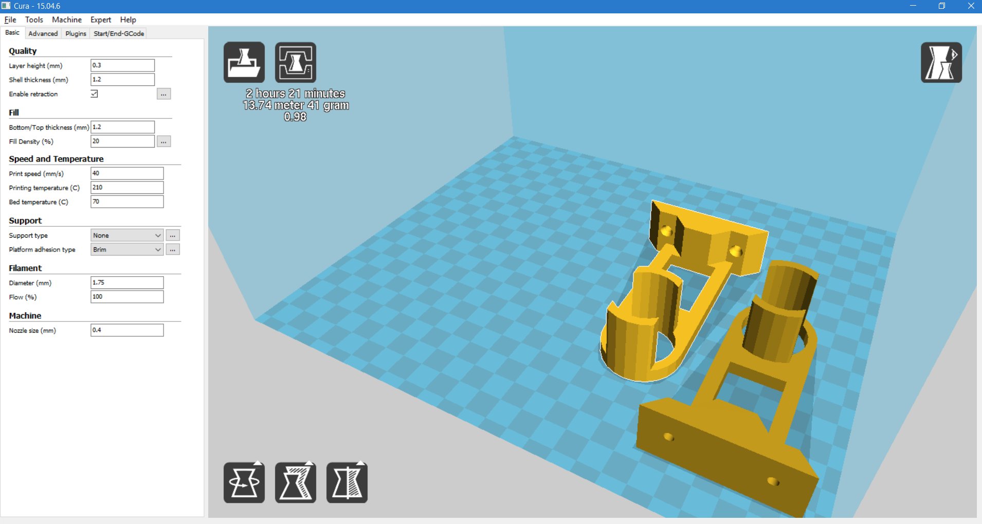
A first draft of (half of) a paper towel holder, ready to be sliced.
Next, the model needs to be sliced. This step involves turning the 3D model into actual print head movement commands that the 3D printer can understand. For this, the model is exported as an .STL file, which is just a list of the 3D triangles making up the surface of the object.
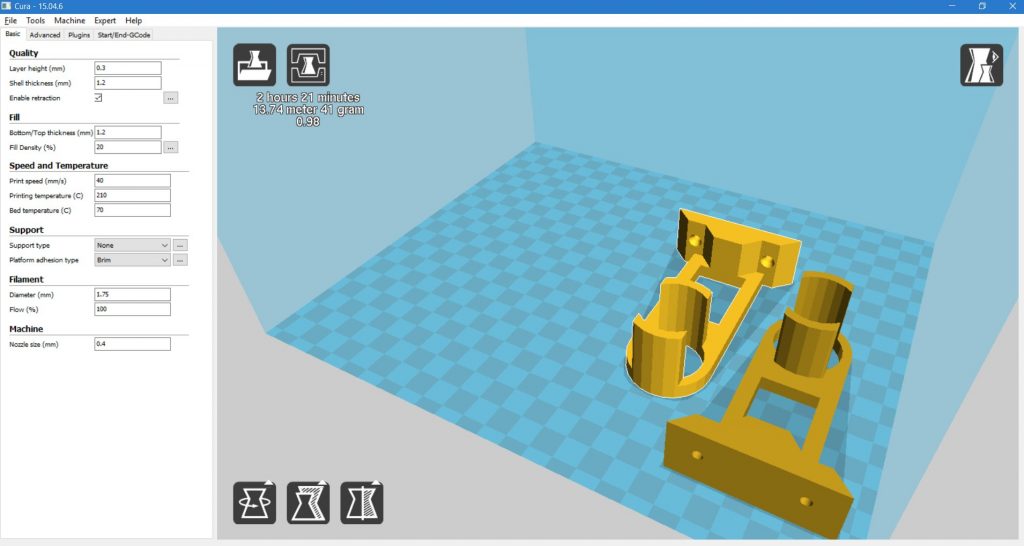
This .STL file is then imported into a slicing program. For now, we’ll use Cura — a popular freeware slicer with a nice GUI interface.
Several decisions need to be made prior to slicing, since this is the step where the specific manufacturing parameters are chosen. Specifically, we’ll go with:
- 0.3mm (300 micron) layer height. This is basically “draft” quality, resulting in coarser layers, but more than adequate for a utilitarian part like this.
- 1.2mm shell thickness. Since I’m using an 0.4mm nozzle size, this means that the slicer will use three outside layers in X/Y.
- 1.2mm top and bottom layer thickness. Similarly to the shell thickness, this means that four top and bottom layers will be printed (since the layer height is 0.3mm.)
- 25% infill. This controls how much of the internal volume is filled with plastic. Larger infill percentage makes for stronger parts — at least up to a point. 25% usually works well.
- 190C hot end temperature. I’ve found this works well for the PLA filament I use.
- 70C heated bed temperature, and
- 40mm/sec printing speed
Once these settings are chosen, Cura will update the sliced model automatically. The next step is to save the resulting .gcode file to be sent to the printer.
The towel holder model is positioned on the printer plate and sliced, turning it into G-Code movement commands.
Finally, the .gcode file is sent to the printer. This can be done directly via SD card, but an easier option is to use OctoPrint — a 3D printer server with a nice GUI interface. When baked into the Raspberry Pi-specific OctoPi image, the result is almost a plug-and-play networked 3D printer.
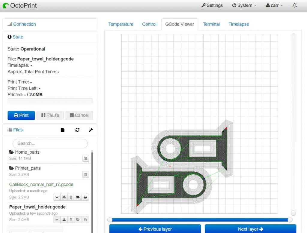
The sliced parts, imported into OctoPrint.
At this point, assuming your printer is already leveled and calibrated, you can just load filament, hit Print, and wait for the parts to appear in a few hours.
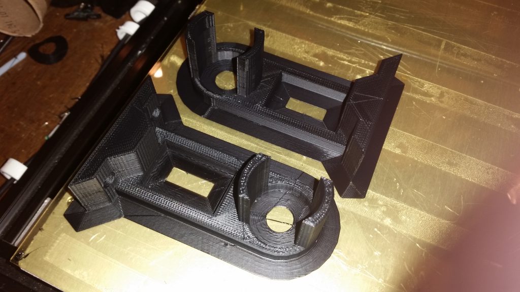
The completed parts, ready for installation.
From design to completed project in an evening. That’s why they call it Rapid Prototyping!