EPROMs

EPROMs are interesting devices. With the advent of Flash memory, they’re not in common use these days. However, they are extremely easy to integrate into hobby electronics, and can serve several functions, including a few off-label ones that I’m currently investigating.

A 64kb (64 kilobit, or 8kB) EPROM, containing 65,536 individual bits.

EPROM stands for Erasable/Programmable Read-Only Memory. As the name implies, it can be erased and reprogrammed, but this is typically not done in circuit. Instead, specialized eraser and programmer units are used to reset the chips and then program them. The new semi-permanent ROM chips can then be used in a TTL circuit just like custom ROM chips; place the address on the address bus, lower ~CE, ~OE, and ~RD, and read the data from the data bus.

EPROM chips are reprogrammed in a two-step process. First, the cells are cleared by setting them to all-ones. Any covering of the optical window is removed, and the chips are subjected to ultraviolet light, which quickly resets all of the exposed memory cells to the “1” state. Programming, done in a separate device, then consists of zeroing out everything that shouldn’t be a 1, much like Michelangelo removed the marble that wasn’t part of his statues.

This is all transparent (pardon the pun) to the user; you simply “bake” the chips in the UV “oven” and then use the programmer per the directions.

Once you understand the process, though, it’s possible to try more interesting experiments. EPROMs are inherently analog devices, with analog amounts of charge stored in each cell.

A closer look at the EPROM die, through a microscope. (Click for larger.)

In the past, others have made clever use of the inherent analog nature of EPROMs by using them to store “digilog” audio — sampled audio, stored as analog charges instead of binary representation. Certainly one of the more unique audio storage methods out there: instead of storing zeroes and ones at every address, eight analog charges were stored.

Due to their optical erasure method, EPROMs can also be used to sense light exposure. Although the data sheets state to “bake” the chips for roughly 45 minutes to an hour for erasure, I’ve found that as little as 20 to 30 seconds is often enough to at least make the chip read as erased. (It may be that longer erasure times help ensure that the 1s remain readable.)

They probably won’t be much use as imaging sensors — even if an image could be properly focused on the split halves of the die, the image would only be roughly 256 by 256, in grayscale. Not exactly high definition. But they might make interesting sunlight-exposure sensors.

Posted in Components, Digital, Electronics, Nostalgia | Leave a comment

Investigating VOR signals, Part 1

Even in the age of GPS, alternate forms of navigation are still around, and still in use. One such technology is VOR (Visual Omni Range) navigation. Despite the questionable acronym, VORs provide useful navigational information by allowing users (nearly always aircraft) to determine their bearing to or from a given nearby station. With two such bearings, position can be determined reasonably accurately.

This direction-finding ability relies on the combination of two signals from the VOR: an omnidirectional reference signal and a swept unidirectional phase signal. By determining the phase difference between the signals, a receiver can determine the direction to the VOR. If the phase signal is received at the same time as the reference signal, the receiver is north of the VOR (since the phase signal is tuned to match the phase of the reference signal when directed north.) If the signals are 180 degrees out of phase, the receiver is to the south. One degree of phase difference corresponds to one degree of azimuth.

Theoretically, given a list of VOR frequencies and locations (readily available online), a GPS-like navigation device could be built to automatically scan the band from 108-118MHz, find nearby VOR signals, determine bearings to them, and solve for the position. Once the phase information is extracted from the signals, solving for receiver position is fairly straightforward. (Aircraft-based navigation systems such as the FMCs on some Boeing aircraft, do this; the FMC can sometimes be seen tuning VORs along the flight path automatically to supplement GPS/INS navigation.

Unfortunately for hobbyist investigations, VORs are specifically designed not to radiate significant RF power at ground level. To minimize interference with other radio services, VOR transmitters include a ground plane at 10′ height, which serves to minimize radiated power at low angles. The specified “service volume” for VORs generally starts at about 1000′ AGL (Above Ground Level).

This makes collecting VOR signals tricky unless you have access to an airplane (or perhaps if you go to the trouble to mount a RPi and a RTL-SDR radio on a quadcopter.) Signal strength, and therefore readability, drop off quickly within a short distance of the VOR, unless you can somehow manage to be at a higher altitude.

This lack of low-altitude signal availability means that VOR navigation is impractical for ground navigation. However, receiving and decoding VOR signals is still a useful exercise — and with the increasing reliability of GPS and other global satellite-based navigation systems such as GLONASS, VOR transmitters may not be around for much longer.

So, to capture a VOR signal for analysis, a field trip was in order. If the VORs won’t transmit appreciable power at ground level, the only option that doesn’t involve chartering an airplane or duct-taping half a kilo of RF gear to a drone is to go pay one a visit.

The Bangor (BGR) VOR transmitter, showing the central omnidirectional antenna, the surrounding phased array, and the groundplane.

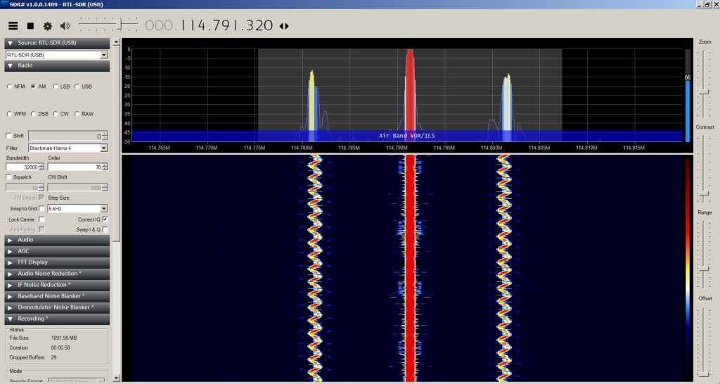
Counterpoise or no, this close to a VOR, you can get a beautiful signal from ground level, even using a $20 RTL-SDR kit from Amazon and SDRsharp software.

SDRSharp spectrum and waterfall plot of the signal from the Bangor VOR. (Click for larger.)

The next step (which will have to wait until I can take a closer look on my workstation) is decoding the signals. One of the nicer features of SDRSharp is its ability to record a slice of the radio spectrum for later playback.

…But be careful what you ask for. Quadrature sampling at 32 bits produces four bytes of data per second, per Hertz of bandwidth sampled. At 16,000kb/sec, this is roughly 2MB per second. At higher speeds, it’s even worse. Roughly ten minutes of recording produced several GB of data, before I realized I didn’t have to sample half the nav spectrum.


This post is dedicated to the memory of my grandfather, Millard C. Carr, who would have been 100 years old today, and who would have thoroughly enjoyed the idea of homebrew VOR navigation, even if he would have pointed out that it’s simpler to use GPS. We miss you, Granddad.

Posted in Analog, Aviation, RF | Leave a comment

Using Math To Answer Questions

The relatively formal and orthodox way that math is usually taught in school usually leaves students knowing how to “Solve for X,” but often isn’t as effective at teaching how to use math to solve problems.

“Golden Ratio” rectangles provide a useful example here. A “Golden Ratio” rectangle has been known to artists for thousands of years as being especially aesthetically pleasing. It has the property that if you cut it lengthwise so as to leave a square, the remaining rectangle has the same proportion as the original.

A golden rectangle. A/(A+B) = B/A. (Image from Wikipedia)

This doesn’t seem to describe how to go about building one — until you rephrase the definition in the language of mathematics. If we call the width X and the height Y (and assume it is placed so X is the longer dimension), we can describe this relation in terms of X and Y, and make an algebraic equation out of it.

Since the original rectangle is X long and Y high, we know that if we cut off a YxY square from one end, the resulting rectangle will have the same dimensions as the original.

So, X/Y (the original ratio) = Y/(X-Y), since Y is now the longer end.

From here, algebraic manipulations give us what we’re looking for — a fixed numerical ratio between X and Y…

X/Y = Y/(X-Y)

Set Y to 1 to obtain the unit ratio:

X/1 = 1/(X-1)

Simplify: X = 1/(x-1)

Cross-multiply to get X(X-1)=1

Distribute and regroup: X^2 – x – 1 = 0

This is a quadratic equation, and is easily solved with high-school algebra. One root of the equation is negative, which doesn’t make sense, but the other is positive: x=[sqrt(5)-1]/2, or roughly 1.618.

This can easily be checked: if you remove a 1 x 1 square from a 1.618 x 1.0 rectangle, you’re left with a 1 x 0.618 rectangle, which has the same aspect ratio (it’s the same shape, just smaller.)

Once you learn to “ask questions” using math like this, you can often find the answer you’re looking for. The art is phrasing the question.


This post is dedicated to the memory of my grandfather, Millard C. Carr, who would have been 100 years old today, and who was partly responsible for my love of technology and engineering, and pretty much wholly responsible for my love of aviation and classic propliners. We miss you, Granddad.

Posted in Math, Science | Leave a comment

Printer, Upgrade Thyself

A while back, I thought I bought a 3D printer.

I really ended up buying a boat. That is, defining a “boat” using the colloquial definition of “a hobby or project that seems to require the investment of ever-increasing amounts of time and money, and which often inspires a love/hate relationship and/or an unhealthy obsession with perfecting the design.”

In other words, open-source 3D printer kits are still really tickets to learning about 3D printers. in particular. and many different aspects of engineering, in general. I already had a decent background in electronics, so apart from a few new minor insights, most of the electronics were pretty familiar. I did learn a lot about extruded rail, various fasteners, timing belts, hot ends, extruders, and some of the properties of plastics. I also learned not to trust no-name power supplies.

But one of the coolest features of 3D printers is that they can be used to make themselves into better tools.

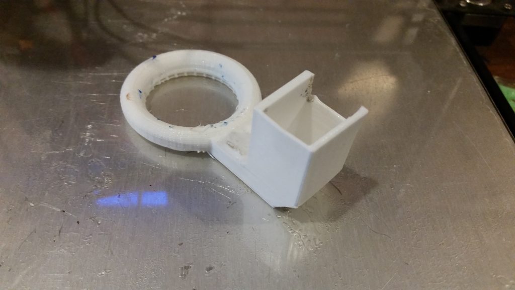
A new fan shroud, as printed, inexpertly hacked on one side, and slightly singed from the hot end.

Somewhere during the process of building the 3D printer, I’d managed to distort the front of the X carriage assembly badly enough that I had to cut it off. (This is the sort of thing that happens when computer engineers dabble in mechanics.)

This meant that the object cooling fan that came with the printer could no longer be attached. I didn’t think much of it until I started trying to fine-tune my part quality, and noticed problems on overhangs. No cooling meant that the plastic was sagging out of position, causing distortions.

Fortunately … I happened to have a 3D printer, if perhaps an imperfect one. This could be solved with the right part!

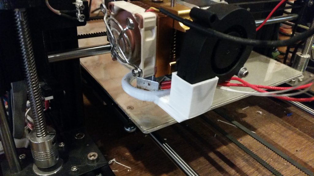
I found a fan shroud design on Thingiverse that looked like it might fit, printed it out, and installed it. This is actually the original idea behind “RepRap”-style 3D printers — that they should be able to make many of the parts for them, themselves. I had to cut into one side and add a washer to get it to work on my printer, but it’s helped significantly with build quality.

The shroud, installed on the printer.

It’s a tiny step towards the Singularity for sure, but it’s still good to have this kind of ability, especially with the recent trend towards consumerism. It’s starting to make sense to make things at home again — and that’s good news.

Because in order to make things, we’re forced to understand them at least a little.

Posted in 3D Printing, Design, Digital Citizenship, Tools | Tagged , , , , | Leave a comment