Relativity, Visualized

“Video games,” at least among non-gamers, are very underrated. When many people think of “video games” or “computer games,” they probably envision either 1980s-style titles such as Pac-Man — or worse, violent, mindless games such as Doom.

Games, however, have the potential to not only be very worthwhile pastimes — but to inform and educate, as well. Occasionally, a particularly well-conceived game can even let players see the world in a new way, and make extraordinary concepts accessible.

A Slower Speed Of Light,” by the MIT Game Lab, definitely falls into this last category. By calculating the visual implications of motion in a world where the speed of light is significantly slower than the usual 300,000 km/sec, players can see for themselves — interactively and in lurid color — the visual effects of near-light-speed motion.

Carl Sagan, of course, famously introduced relativistic motion to viewers of Cosmos back in the 1980s, along with a good explanation of why these effects occur. With modern computer technology, though — notably high-performance graphics cards — computers can bring such worlds to life and make them interactive.

The game takes only a few minutes to complete, but is an enlightening experience (pardon the pun). It’s a free download, and available for Windows, Linux, and Macintosh computers. Check it out!


Posted in Games, Science | Leave a comment

The Making of Pitfall

For many Generation X’ers like myself, the Atari 2600 brings back memories of many fun hours spent playing video games. We didn’t know it back then, but the 2600 was little more than a CPU, a crude video subsystem, and a sound chip bundled into a console. Atari 2600 cartridges contained a ROM chip, which had to more or less create the entire game from scratch. All the magic was done with really clever assembly-code (or even machine code) programming. It’s all described in a fascinating book called Racing The Beam.

I recently came across a neat video on YouTube where David Crane (the creator of Pitfall and the even more impressive Pitfall II) gave a talk on how the amazing effects in these games were accomplished.

The Atari 2600 was, initially, really only designed to play two games: Pong and Combat. Its hardware was built around two “player” sprites and three “missile” or “ball” sprites. Not only that, but the display was built one line at a time. The game code in the cartridge had to keep track of which line it was on and then display the line when the right time came.

It had to do all this in real time, before the beam swept across the screen again!

How did Crane and other developers convince this system to produce complex games such as Pitfall? By employing every trick in the book, and writing more than a few new ones into the margins for good measure. (Why did the background graphics in some games look weird? That was actual machine code being displayed, due to a lack of space to store bitmaps!)

Crane’s talk (including a Q&A session) is just over an hour long — but this is time well spent for anyone interested in the nuts and bolts of making computer games. These guys made magic out of almost nothing.


Posted in Assembly, Coding, Digital, Nostalgia | Leave a comment

“Wye Knot”

I came across an interesting puzzle a while ago (stated in one of the excellent Feynman Lectures on Physics): What is the resistance between two opposite corners of a cube made from 1-ohm resistors?

At first, the problem looks like it might just be an exercise in resistance simplification using the well-known laws of parallel and serial resistances: Serial resistances add linearly, and parallel resistances follow 1/R = 1/R1 + 1/R2 etc. Unfortunately, this one isn’t quite so simple — three resistors meet at each vertex of the cube, and no two are directly parallel to or in series with each other.
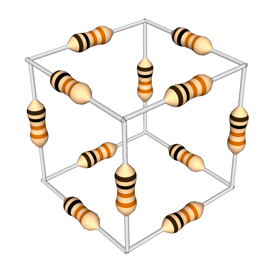
A cube of 1-ohm resistors. What is the equivalent resistance between opposite corners?

One solution to this problem is to use the Wye-Delta conversion formula. Each of the corners of the cube is the center node of three resistors in a wye configuration.  These three resistors can be replaced, and the central node removed, by following the formula:

Wye-Delta conversion formula

(formula from Wikipedia)

Rp in the formula is the sum of products — that is, R1R2 + R2R3 + R1R3.
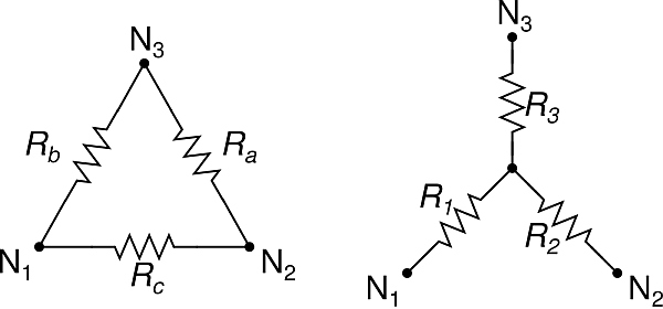
Delta and Wye configurations. (Click for larger.)

(image from Wikipedia)

Using this formula, corners of the cube where three 1-ohm resistors meet can be removed; the three outer vertices of this wye are then connected by the equivalent network of one 3-ohm resistor between each pair of vertices (see image).
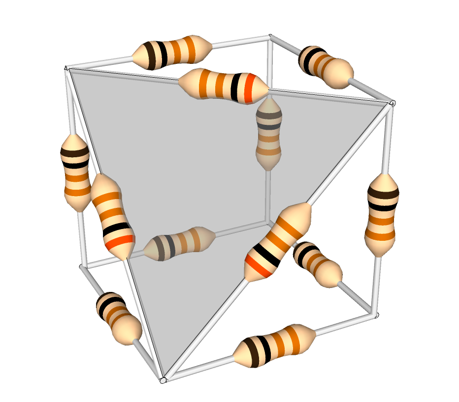
 

The cube, with one (shaded) corner transformed. Note the 3-ohm resistors.

One way you can think about this is that, initially, the resistance between any two nodes of the wye is 2 ohms (the inbound resistor plus the outbound resistor.) In order for the delta network to be equivalent, this resistance must be the same; the value of the delta resistor connecting those two nodes, in parallel with the sum of the other two delta resistors (for the long path around the triangle), must equal the original value of the resistance between the two nodes of the wye. For a wye of 1-ohm resistors, this is 3 ohms, since a 3-ohm resistor in parallel with a 6-ohm equivalent will equal two ohms. (1/3 + 1/6 = 1/2)

You can continue reducing the network in this way — but it turns out that symmetry and a little common sense provide an easier way to solve the puzzle.
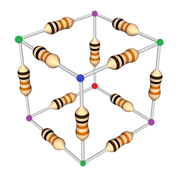
The cube, with equipotential points shown, assuming resistance measured between blue and red. (Click for larger.)

Suppose that in the cube above, a voltage source is connected between the blue and red nodes. The resulting current can be used to determine the overall resistance. To calculate this without resulting to Wye-Delta conversions, note that all of the “purple” nodes are at the same voltage (due to symmetry), and all of the “green” nodes are at the same voltage (also due to symmetry). Because of this, the three purple nodes and the three green nodes can therefore be connected by wires in order to simplify the analysis. Because no voltage difference exists between the nodes, no current will flow across these wires, so the nature of the circuit hasn’t been fundamentally changed.

Here is a schematic of the original cube configuration…
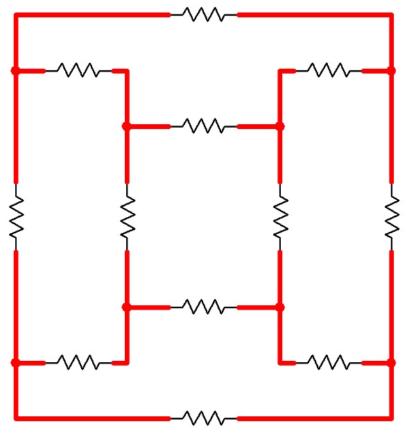
A schematic for a circuit electrically equivalent to the Resistor Cube. (Click for larger.)

…and here is a schematic of the cube with the equipotential connections in place.
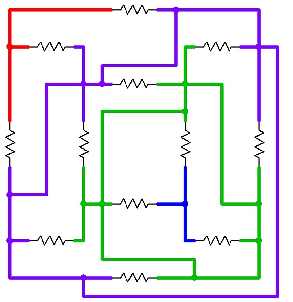
The same schematic, with connections added between the equipotential points. (Click for larger.)

The problem now becomes trivially easy. The blue node is connected to the green node via three 1-ohm resistors; the green node is connected to the purple node via six 1-ohm resistors; and the purple node is connected to the red node via another three 1-ohm resistors.
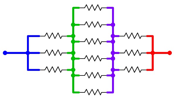
The equivalent circuit -- a simple series-parallel network. (Click for larger.)

The total circuit resistance is therefore 1/3 + 1/6 + 1/3 ohms, or 5/6 ohm.


Posted in Analog, EET201, Electronics, Fundamentals, HOW-TO, Math | Leave a comment

Arduino on Steroids

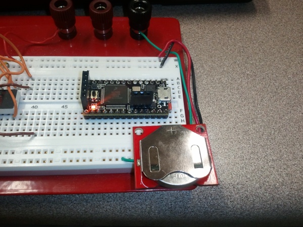
The Teensy 3.0 is a cool little dev board. It’s Arduino-compatible (from a software perspective, anyway), breadboardable, and only about $20US.

The Teensy 3.0 running from a 3.7V coin cell on a breadboard. (Click for larger.)

It also runs a 48MHz, 32-bit Arm processor, making it not only easy to use, but a speed demon. If that’s not enough, it can be overclocked to 96MHz reliably enough that this is left as an option in the Arduino plug-in code provided with the board.

Like all Arduinos, the Teensy can be programmed from the Arduino IDE, although the various differences mean that you’ll need the Teensyduino mod before you can get up and running. Install the latest Arduino IDE first, then Teensyduino.

With additional features such as digitalWriteFast(), the high speed of the Teensy 3.0 can be put to use. Within a few minutes of setup, I had an I/O pin toggling at speeds as high as 50MHz.

Dev boards like this can come in handy for all kinds of projects. A board like this has the horsepower to handle color displays with complex graphics, autopilot and other control-system-type computations, and many other tasks — even simultaneously.

Posted in Arduino, C, Coding, Digital, Electronics, Toys | Leave a comment