Mystery Resistance

As part of a recent Girls, Inc. summer camp activity we hosted at work, I designed and produced about a dozen Electronic Mood Rings. This turned out to be a learning experience in many ways.
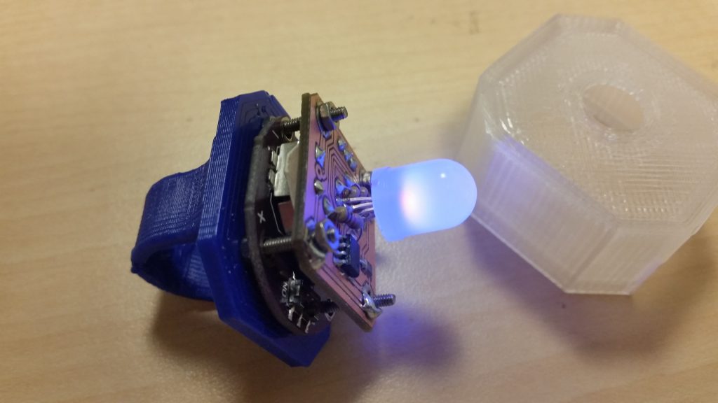
The prototype Electronic Mood Ring.

I learned that, while SMT devices are tricky to work with, SOIC parts can be reasoned with if you use a good iron, silver-bearing solder, and generous amounts of flux.

I learned that 1206 SMT parts are very forgiving but still a pain to solder by hand. Stencils and reflow may be the way to go, here. Or just outsourcing it.

I learned that PIC12F1571 microcontrollers should be able to run at 32MHz internal clock speed. Nice! Except that mine didn’t want to turn the PLL on, and I had to settle for 16MHz because it was easier than continuing to argue the point. Besides, the new BRW instruction means no more mucking about making sure my computed GOTO tables don’t cross 8-bit boundaries. So I can forgive a few quirks.

I learned that I still don’t know how to solder true SMT parts such as NeoPixel Mini PCBs. Might need a reflow plate for those.

I learned that, for whatever reason, clear PLA filament just will not print reliably on my machine. Purple printed fine. Pink printed fine. Blue printed fine. Even black cooperated and printed without problems, which isn’t always a sure thing. But three different reputable brands of clear filament caused 95% of the problems. It jammed. It blobbed. It strung. It refused to adhere to the bed at one point.

Bizarre.

I also learned not to trust knockoff parts. The battery holders I bought only worked properly once I figured out you need to wedge a strip of aluminum foil under the negative contact, to get it to work. Pure Chinesium. Well, to be fair, they were a lot less expensive, and worked well other than that. My guess is they were tested with a different brand of battery.

The most surprising thing I learned about was the Phantom Voltage Divider.

I should explain. The battery holders I was using included a small circuit board, a CR2032 battery, a SPST switch, and metal contacts and traces. That’s it. No resistors or other electronics. Bare-bones simple.

So it was perplexing to put a 3V battery in and, with the switch off, measure 1.8V out. Changing voltages like that requires either active electronics or at the minimum, two resistors. There were no resistors anywhere on this board. What was happening?

Lack of sleep due to optimistic scheduling was what was happening. It turned out that the meter was correct. It really was reading 1.8V, and it was all my fault. Well, mine and the meter’s.

Multimeters (real ones) have a finite input impedance. This can be a calibrated high value of, for example, 10M ohms on professional desktop meters like the Agilent 34401A, or a similar, uncalibrated but high value on handheld meters. No doubt the Fluke that I was using has a well-understood input impedance. Or at least a high one.

Most of the time, this high impedance means that the meter won’t have a significant effect on the circuit voltage. What little current flows through the meter is lost in the (much greater) flow of current through the circuit.

This circuit was off, though — but still read 1.8V. Due to lack of sleep, it took me a few minutes to figure out the answer. I was the missing resistor. Part of my hand was in contact with the positive terminal on top of the battery, and a few microamps of current were leaking through my hand to the meter. Since the meter had roughly the same input resistance … it and I formed a voltage divider.

The laws of physics have a sense of humor, I guess.

Posted in 3D Printing, Design, Digital, Drexel, EET201, Electronics, Fundamentals, PIC Microcontrollers | Leave a comment

Virtual Confusion

Okay, I get it. FreePCB is kind of dated and I should really learn Eagle at some point. But it’s still a useful tool — at least, when Windows doesn’t get in its way.

FreePCB, unfortunately, defaults to storing project files in a “projects” folder in its own working directory. This makes some sense, but ultimately documents are supposed to be stored in the proper place — not where the program is installed.

I agree this is best practice — but Windows (since Vista) takes things a step farther, as I found out today. If a 32-bit program is not running with administrator privileges and isn’t compiled for Vista or later, that means it can get “virtualized.”

What this means, in practical terms, is that, since Windows no longer allows programs to write to the “Program Files (x86)” directory structure, it makes a shadow copy of this structure and redirects all writes to that.

The problem arises when you want to, for example, go find these files that the program has written. They’re nowhere to be found in the “Program Files (x86)” structure — and yet, the program can exit, relaunch, and reload the files with no problem at all. Witchcraft!

Figuring that the files had to be somewhere on the drive, I went back to first principles and ran a search.

c:\>dir /s /b *.fpc

After a brief search, the files were found in the c:\Users\…\local\VirtualStore\ substructure. A quick Google search turned up the following explanation, paraphrased above.

Mystery solved. But some notice would have been appreciated, MS. Maybe one of those pop-up boxes you’re so fond of using to steal the focus at the worst possible times. Or something.

Posted in System Administration | Leave a comment

Pointers in BASIC

BASIC, as Rodney Dangerfield would have said, “don’t get no respect.” Even when using modern dialects like FreeBASIC, which allow custom user types, modern-style functions and subroutines, encapsulation, and more, there’s still very much a “Real Men Program In C” attitude.

C is deservedly famous and influential, of course, but it’s often tedious to write small, proof-of-concept programs in C. If a new idea about, say, cellular automata strikes you, it’s very easy to write a few lines of BASIC code and be testing it — in full-color HD.

But still, C proponents say, it’s a “toy” language. It doesn’t have pointers or linked lists or all that.

Except — it does. In FreeBasic, at least, the familiar malloc() and sizeof() functions are available, and memory truly can be dynamically allocated, deallocated, and manipulated as pointers.

Here is a short example that demonstrates creating and printing out a simple linked list in FreeBASIC. Memory is dynamically allocated and user type fields are accessed with the -> operator, just as in C.

'Pointers in FreeBASIC
 'Example: Create and print out a short linked list

'M. Eric Carr / Paleotechnologist.Net
 'Contact: eric (at) the above domain

'Define a simple user type
 type listItem
 payload as double
 link as listItem ptr '"next" is a keyword in BASIC; we can't use it.
 end type

dim as listItem ptr head, current
 dim as integer n

'Teach FreeBASIC about NULL
 const NULL = 0

'Set up the first item in the list manually
 head = allocate(sizeof(listItem))
 current = head
 current->payload = 0
 current->link = NULL

'Use a for loop to add nine more items to the list
 for n=1 to 9
 'Starting conditions: current points to last item in the list.
 current->link = allocate(sizeof(listItem))
 current = current->link
 current->link = NULL 'For safety
 current->payload = n^2
 next n

'Read them back using a while loop, looking for the NULL at the end
 current = head
 while current <> NULL
 print current->payload
 current = current->link
 wend

'Done. Wait for a keypress before exiting.
 sleep

(Don’t tell the use-C-or-die types, but FreeBASIC can use inline x86 assembly, too.)

Posted in BASIC, C, Coding, HOW-TO | Leave a comment

DIY Ionic charging

The Fitbit Ionic is a neat little device, capable of tracking various different exercises as well as providing continuous heart rate monitoring and sleep quality tracking. It is quite well-connected as well, with WiFi, BlueTooth, and NFC capabilities. It can stream music to Bluetooth headphones, sync exercise data over WiFi, and pay for your snacks via NFC.

The battery life is better than I expected, too. It will run for several days of typical use without charging. If I don’t use the GPS tracking feature much, it can sometimes go roughly a week between charges. It even sends you an email when it’s low on energy. Welcome to the future.

The one drawback, of course, is that (being waterproof) the Ionic uses a proprietary MagSafe-like connector for charging. And naturally there’s no information readily available about what pins are what. So if your Ionic’s battery is low and you don’t have its charging cable handy, you’re pretty much out of luck.

Time for some detective work.

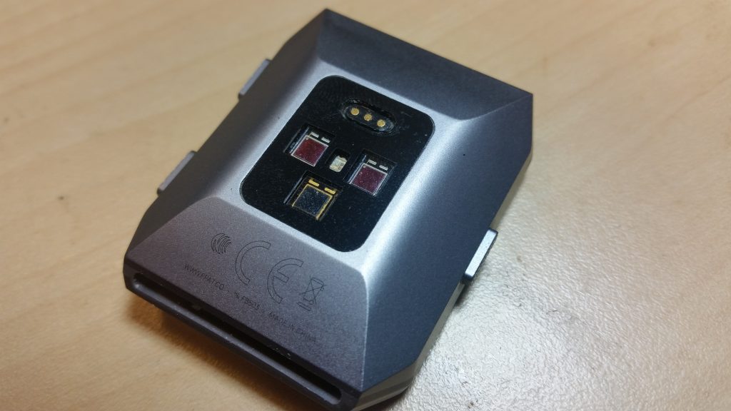
The back of the Ionic. The three gold pins are for the charging cable.

I knew that the charging connector was symmetric; it will work in either orientation. So the two outside pins must have the same function. This, with the fact that the charging cables don’t look like they contain more than just wires, means that, in all likelihood, either the center pin is ground and the outer pins are 5V, or the other way around. If I were designing a watch like this, I’d go for one 5V pin in the center and two ground pins. Let’s try that, I figured.

So I hacked together a small breadboard-based adapter and connected it to a current-limited lab power supply. (The current-limited part is important: if you get the polarity wrong and forward-bias a protection diode, you don’t want your power supply dumping three amps of current through it. That’s how the magic smoke gets let out. With the current limiting, the supply will back off on the voltage if too much current is flowing. This gives you time to disconnect it before anything gets too warm.)

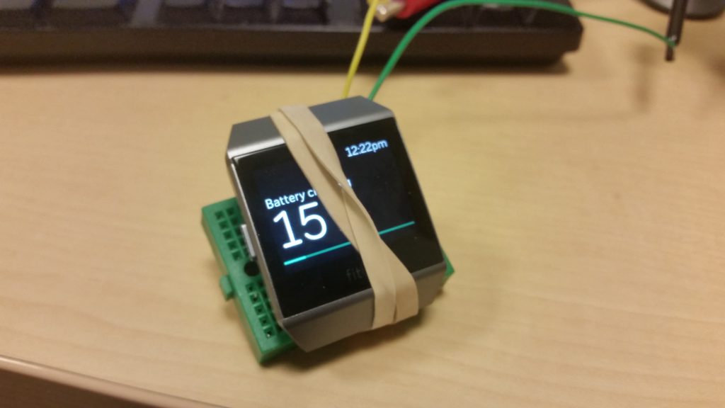
I limited the power supply to 300mA and gave it a shot. With a little adjustment to get it to sit on the pins properly, it works, drawing about 180mA at 5V.

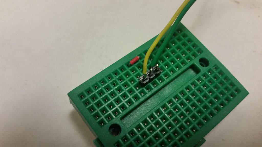
Details of the connections. The outer two pins are tied together and to Ground. The center pin is 5V.

The Ionic, less its wristband, on its makeshift charger.

The adapter itself is straightforward: Three standard row-connector pins, with the outer two bent slightly inwards to match the Ionic’s connector pitch. The outer two are connected together and to Ground (black, on a USB cable); the center pin is connected to a 5V supply (red, on a USB cable).

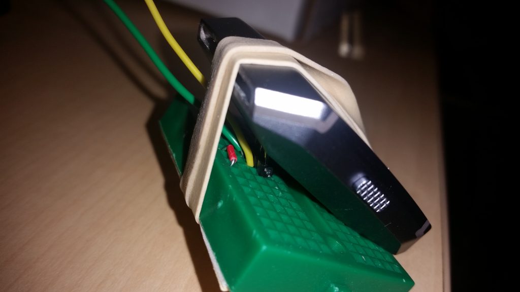
The Ionic on the makeshift charger, showing some of the connections.

Disclaimer: Use this technique at your own risk; this is a hack, not an engineered solution. It worked for me, and properly implemented, should work for anyone, but will certainly void your warranty if you get it wrong (and maybe even if you do it right.)


Posted in Hacks, HOW-TO, Power, Reverse Engineering, Toys | Leave a comment