Artifact-Free Metrology!

With today’s vote in Versailles, we will soon have a consistent measurement system that isn’t based on a chunk of metal kept in a vault in Paris. Because modern experiments have made it possible to determine the value of universal constants like Planck’s Constant to extremely high precision, the members of the General Conference on Weights and Measures were able to confidently vote to switch us to a new definition of the kilogram — one based on setting Planck’s Constant to an arbitrary value based on careful measurement, and redefining the kilogram based on that.

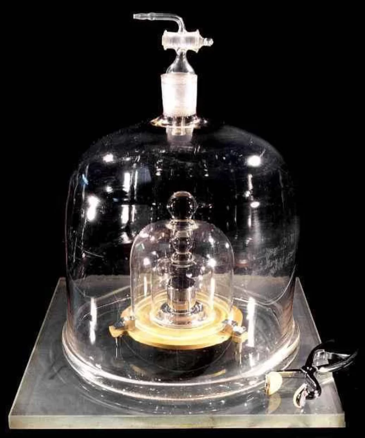
The International Prototype Kilogram (IPK), or “Le Grand K.” (Image credit: BIPM)

Measuring h to this accuracy involved two different types of experiments, to not only allow for replication but independent confirmation of results using a different method. When two such dissimilar experiments agree with high precision on anything, you’re on the right track. In this case, the results of sensitive Watt-balance measurements were compared with the results of measuring the mass of nearly perfect spheres of a single isotope of silicon to high accuracy. These spheres are probably the most geometrically perfect things anyone has ever made.

With this new definition, set to officially take effect on May 20, 2019, the accepted standard values for several SI values will change very slightly. For most practical purposes, though, this change will be so small as to be lost in the noise. That’s the reason for taking such pains to measure h as closely as possible — we want the new definition to match the old, artifact-based one as closely as possible (since that’s what everyone’s devices are already calibrated to.)

What does this mean? If you love science and like to see it done right, this is an amazing step in the right direction. Going forward, all of the SI units will be defined in terms of natural physical constants that anyone can measure.

Veritasium, not surprisingly, has a great explanation video.

If you’re worried about the measurements changing, don’t be — unless you work with precision measured in parts per billion. It’s a good time for Le Grand K to retire. It will no doubt find a place of honor in a museum — as a 1.0 kilogram mass that used to be the 1.0 kilogram mass.

Because having to explain that your definition of the kilogram is losing weight is more than a little embarrassing.

Posted in Current Events, Digital Citizenship, Electronics, Fundamentals, Mechanical, Science | Leave a comment

Resurrecting the Sinclair

The first computer I ever used was a university mainframe, accessed through a teletype terminal in my uncle’s apartment. It played a mean game of Tic-Tac-Toe (and presumably helped with my uncle’s Finance dissertation.)

The second computer I ever used, the first one I ever owned, and the one on which I learned all kinds of horrible 1980s-BASIC programming habits on, was a Timex-Sinclair 1000.

The Timex-Sinclair 1000. (Thanks, Mom and Dad. Best present ever!)

The TS1000 had the distinction of being the first home computer under the magical $100 mark. While still not cheap, that put it within reach of normal people. The Personal Computer revolution was beginning!

The TS1000 is based on the deservedly popular Z80 microprocessor. Sinclair Research combined the Z80 with a custom video card, a ROM containing the BASIC programming language, and 2KB of RAM.

The Timex-Sinclair 1000 system board.

The keyboard no doubt contributed to the low cost of the Sinclair, as it was a very cheaply manufactured membrane keyboard which connected through a slit in the top case to plug onto the system board. These worked marginally well for a few years, but would inevitably become brittle with age. When this happened, the conductors would develop hairline cracks. If even one of the thirteen keyboard lines broke completely, a whole section of the keyboard would become unresponsive. It’s rare to see one working these days. Neither of my two did…

My original keyboard, showing the deteriorated connector.

Not only did these old keyboard connectors break — they would often break off in the connector, requiring exploratory surgery to clear them out before the connector could be inspected, cut cleanly before the break, and hopefully reinserted if it hadn’t become too short.

That’s not supposed to be there. Not without the rest of it, anyway.
Fortunately, it came right out.

Nostalgia being what it is, many of my fellow middle-age geeks fondly remember the Sinclair, keyboard problems and all. So I guess it’s not surprising that someone came up with a solution. I found a site selling replacement ZX81/TS1000 keyboards for about $15 or so. Not a bad price at all to resurrect an old (if temperamental) friend!

The new keyboard.

A few weeks later, the keyboard arrived. The key action is much better than the original, but the tinned metal connectors on the end appear to be intended for soldering rather than for plugging into the keyboard connector.

Tinned wire connections on the new keyboard. Good for soldering, not so good for staying in the old socket.

Never one to design an engineered solution when a perfectly good hack would do, I cut up a wire-wrap socket (probably half as expensive as the keyboard — they’re Not Cheap). It’s not going anywhere, now.

A hacked-up wire-wrap socket works perfectly.

With the new keyboard, the Sinclair is back from the dead! Now to fix up the case a bit and work on some peripherals — or at least a way to save and load programs from an mp3 player or something.

It’s alive! (And so is the 1970 Ford TV that I used to use with it.)


Posted in BASIC, Nostalgia | Leave a comment

JLCPCB

The Maker revolution generally encourages adding to the repertoire of processes that can readily be done at home. Desktop soldering stations, multimeters, and power supplies have been available for decades; oscilloscopes have been getting more affordable recently, and the recent explosion of 3D printer technology has really made a lot of things possible.

The production of good quality circuit boards, however, is still a challenge. I can produce more-or-less-acceptable 2-layer boards on our LPKF PC board mill at work, but producing good circuit boards at home either requires a lot of patience and toxic chemicals or a circuit board mill costing probably into four figures. And even then, the boards produced lack through-hole via plating, solder mask, and silkscreen, and are generally cruder and less reliable than any industry standard. Some processes still require expensive equipment to do well.

Some circuit boards, freshly milled on the LPKF desktop mill at work.

Recently, however, a number of DIY-friendly, low-quantity solutions for getting PC boards made have become available. I recently placed an order for ten PC boards with JLCPCB.com. Here’s how that went, and why I now have another go-to vendor for my list of favorites.

The process starts by creating a set of Gerber files. This is usually done automatically by PC board CAM software like Eagle CAD. I’ve been using FreePCB for years to make our boards at work, so I decided to see how it did.

CAD view of the top of the board

The test board (which needs several revisions, but that’s expected) is mostly a 24VAC-to-5VDC power supply for a Raspberry Pi and relay module, along with some extra connections to make hookup easier. I created the design in FreePCB, exported the Gerber files, and then uploaded the design to JLCPCB’s site. Design took a few hours; the upload and ordering process took maybe half an hour since I was unfamiliar with it. Now that I’m signed up and everything, future orders will probably take more like ten minutes.

…and that was it, really. I got a couple of emails later that day saying the boards had started production (even though it had to have been something like midnight in Shenzhen.)

Less than a week later, an express DHL shipment arrived. The boards look quite good, especially considering I paid $2.00US for the whole ten-pack. Shipping was just under $20, but that’s expected for essentially overnight shipping from China.

Ten boards, delivered in about a week, for $20 or so. Not bad.

I populated and soldered the first one off the stack (I only really needed one, but it’s the same price for ten), and it works well so far. Custom good-quality PCBs for twenty cents each (plus shipping). I love living in the future.

Posted in Electronics, Resources | Tagged , , , , , | Leave a comment

OpenSCAD

The traditional way to create models for 3D printing is to design them using a CAD program. Typically, the designer will draw a few rough shapes to build the basic outline of the part, extrude them, then add other features and/or remove material for holes, bezels, cutouts, etc. This works well for many designs, and is deservedly by far the most popular way of creating 3D models. However, it’s not the only available method. Creating models in code, from mathematical operations, opens up design possibilities that would be difficult or impossible to reproduce manually.

If you want a hole in your model, for instance, it’s generally straightforward enough to draw a circle and extrude it into the material. But if you want four hundred of them in a 40×10 matrix, that could take a while. And smooth, mathematical designs like a Moebius strip can be nearly impossible to create by hand.

A Moebius strip and the code to produce it in OpenSCAD. (Click for larger.)

OpenSCAD is a Free, Turing-complete modeling language for the creation of 3D models based on mathematical primitives. Basic shapes such as cubes, spheres, and cylinders can be scaled, translated, rotated as well as added to, subtracted from, and intersected with other objects. Control structures such as for loops allow for the automatic assembly of more complex objects like corkscrews based on the mathematical formulas. Define the shapes, and OpenSCAD creates the model.

Printing your creations is straightforward. After finishing the code for your design, press F6 to render your design (using a more accurate method than the quick preview). Once rendered, the design can be saved as an .stl file to be sliced into g-code by the slicer of your choice.


Posted in 3D Printing, Coding, Math, Tools | Tagged , , , , , | Leave a comment