PCBWay

It’s always fun to learn of new processes and capabilities — especially when processes which used to be prohibitively expensive themselves benefit from new technologies such as CNC and 3D printing.

Since our department bought an LPKF PC board mill in 2010, we’ve had the in-house capability to produce what I call “1.5-layer” boards. Our mill can do the insulation passes on the top and bottom — and I have it dialed in well enough that the solder pads are viable on both sides and aligned. However, the process doesn’t plate vias. Any connections between the two sides of the board must rely on a manually-soldered lead through a hole. With complex designs involving dozens of vias, this adds not only hours of benchtop time but dozens of potential failure points to the board.

The existing solution has been, wherever possible, to keep all traces on the bottom side of the board, and use resistors and similar components as natural bridges across other traces. This has worked well for relatively simple boards like the TIL311 replacement hex decoder — but even this is pushing the style close to the reasonable limit. For more complex boards, 2- or 4-layer processes are needed.
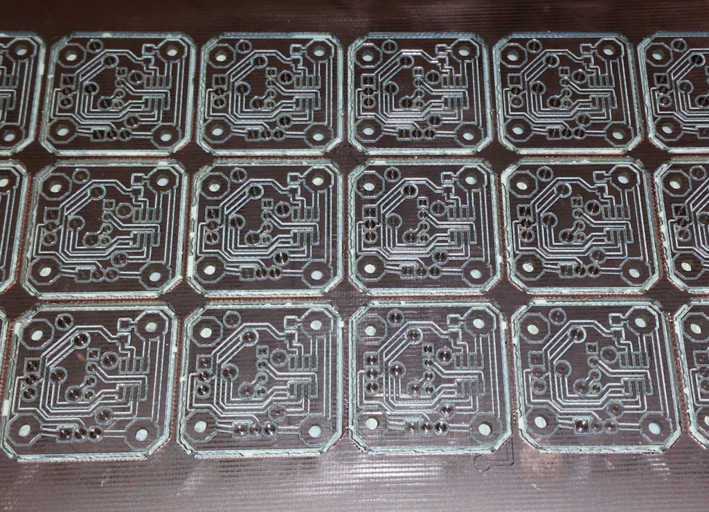
The old-style boards, as milled on the LPKF.
(These were for a Mood Ring project for a local Girls, Inc. engineering activity.)

These days, provided you can wait a few days for the boards, there’s a better option. Modern PCB houses like PCBWay can accept your Gerber files over the ‘Net, apply a DRM check, and produce them with far more options than in-house production could provide. Even with shipping from China, you can have your boards in just a few days.

This capability has been available (for a steep price) for a number of years now — but recently, Just-In-Time manufacturing techniques and high levels of automation have meant that even small, custom orders can be turned around in a few days at surprisingly low cost.

Full disclosure: PCBWay kindly provided the boards ($41 value) for this Hex Decoder project free of charge in return for a writeup, but this review is my honest opinion — as is everything on this site.

With more students (and seemingly fewer remaining hex decoder boards) each year, I needed to make up some more hex decoders for next year’s Microprocessors class. PCBWay had recently contacted me, asking if I would be interested in reviewing their services, so I thought this would be the perfect opportunity. (Making boards with the LPKF is fun but time-consuming anyway, and there’s always the chance that something will go wrong and you’ll have to start the batch over. Maybe if I had an apprentice?)

So I packaged up the original FreePCB design into a semblance of normal-looking Gerber files, and uploaded it to PCBWay’s site. Somehow it passed the DFM checks, and within a few days (I may have submitted it on a Friday night right before Lunar New Year), a package with 20 boards was on its way to me.
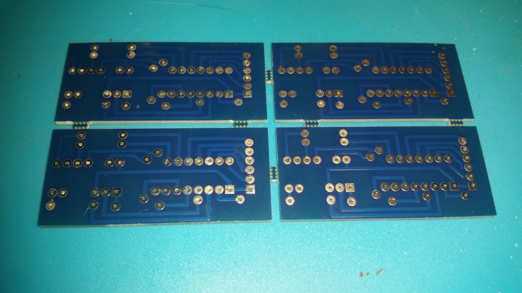
The “business end” of the boards.
(Although the new process is capable of plated vias and reliable thin traces,
this design still reflects the original oversized, single-layer-or-bust style.)
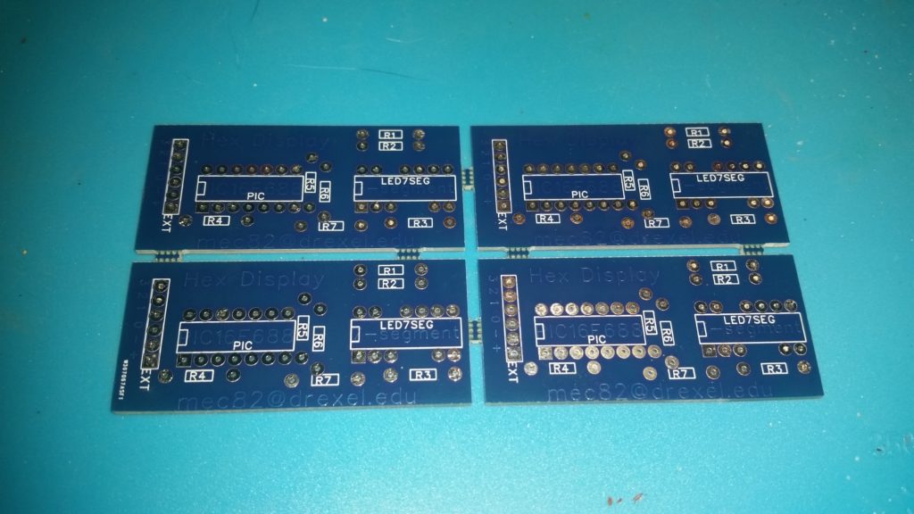
The top layer of the boards.
The blue-on-blue text is a holdover from when this text was cut on the LPKF.
It was designed on the copper layer; I should have moved it to the silkscreen. Oops.

PCB design cognoscenti (of which I am not one!) will note that the pads are significantly larger (90 mil) than normal (50ish mil?), and the traces are quite large, too. This was because the original board was designed to be produced in-house using our PC board mill. This process produces untinned, hard-to-solder-to pads — and thin traces sometimes don’t survive the cutting process. Because of this, the DFM rules I used (25-50 mil traces, 90-mil pads on 100-mil spacings) could probably be met by a competent blacksmith.

PCBWay still manages to make it look pretty good, but I’m looking forward to designing boards with modern tolerances. No doubt fine-tuning the milling process would help, but outsourcing to a modern PC board house makes for much more reliable boards. So far, I’ve tried PCBWay as well as JLCPCB, and had very good results with both. PCBWay’s site seems a little easier to use, and they have some nice design sharing/selling features, and great customer support.

Once I found my old plans and got the necessary parts together, soldering was very easy; the plated pads and solder mask mean the solder goes where it should and not where it shouldn’t. Through-hole soldering is a piece of cake, and even SMD components — which are very experimental on the LPKF process — should be straightforward.

The results of a quick-and-dirty rush solder job.
Everything worked great.

Bottom line: Even though PCBWay kindly comped the boards for this project, I’m impressed. These are decent, professional-quality boards with good tolerances, plated vias, solder masks, silkscreening, and more. They’re far better than we could make in-house, for something like a few dollars each — maybe even less, in quantity — and they can arrive in a week or two. If they’d only add yellow or gold silkscreen, we could even have them in school colors.

PCBWay isn’t the only good PC board house out there, but they provide good boards quickly at a nice low price, and have an easy-to-use site. Check them out.

Posted in Design, Digital, DrACo/Z80, EET325, Electronics, PIC Microcontrollers, Reviews | Leave a comment

Bearing Raceway Speedometer

One of the projects I’ve been meaning to build for a while now is an accelerator / elevator for 12mm steel bearing balls running in a 3D printed track. This will mean experimenting with coil pulse timings and durations, and it would really help speed things up if this could be automated.

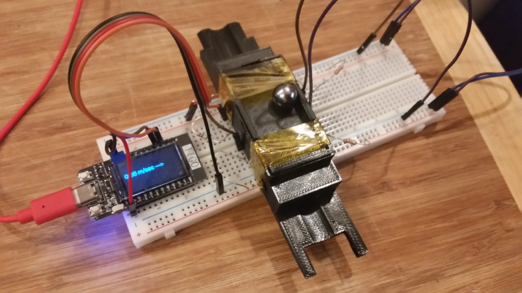
So, Step 1 was to build a speedometer. (After all, it’s difficult to improve something if you don’t measure it.) Microcontrollers, especially fast ones like the ESP32 family, are really good at measuring differences in timing. If you set photodiode gates across the track from a fixed LED and have the microcontroller scan the photodiode output, it can sense when the beam is blocked, to high precision (microseconds). If you place two of these a fixed distance apart (I’m using 50mm), you can calculate average velocity between them by V = D/T.

The .stl for the frame itself is available here on Thingiverse. It should be printable without supports (the ceiling of the ball channel is arched to allow for airflow and for printability.) A Gikfun photodiode set is used to sense when the ball blocks two light beams 50mm apart. The difference in timing, along with the fixed distance, allows speed to be calculated. This is displayed on the screen in m/sec, along with an arrow showing direction of motion.

Next step, build an accelerator and use this to automate dialing in the parameters. (With the addition of some ramps and such, it wouldn’t make a half-bad experiment for our department’s undergrad Metrology course, too.)

Posted in 3D Printing, Arduino, C, Coding, Digital | Leave a comment

Digital Microscope

One of the coolest things about technological progress is that it feeds on itself. New technologies generally make new processes feasible (or possible), and this inevitably leads to new toys tools that we engineers can use to make even cooler stuff.

Recently, inexpensive consumer-grade digital “microscopes” have gotten pretty good, at least in terms of imaging. For around $65US, you can get a CCD “microscope” that can produce clear images at something like 60x magnification and can resolve objects down to something like 10-20 microns. While this isn’t anywhere near the performance of a professional microscope, it’s a very useful benchtop tool — with a few caveats.

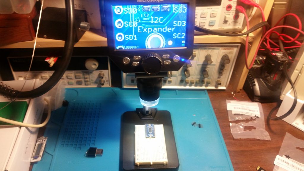
The microscope, examining an I2C expander from Adafruit.
(This is the minimum zoom achievable with the stock stage.)

The biggest problems are related to the mounting. The camera may well have a 10MP sensor (hard to say; the images come out at 10MP but are .jpgs and may be upscaled) — but the mounting stand is cheap and tends to shake and flex when used. Maximum zoom is limited by the optics, which can only focus down to a minimum distance of a few centimeters from the object. Minimum zoom is limited only by the maximum height to which the mounting can move the camera; the optics themselves are capable of focusing on objects at infinity. Vertical movement is accomplished by a rack-and-pinion system which, being mostly plastic, binds up, preventing smooth motion, and has far too much backlash / hysteresis.

Many of these problems can be corrected by mounting the camera securely to a better gantry, such as a 3D printer or CNC mill. For board-inspection work such as the inspection of solder joints, the existing stage works reasonably well. Still, an additional $10 or $20 cost would have been a small price to pay for a more solid mounting and maybe metal or even nylon gears.

Once you work around the mounting limitations, though, the images aren’t bad…

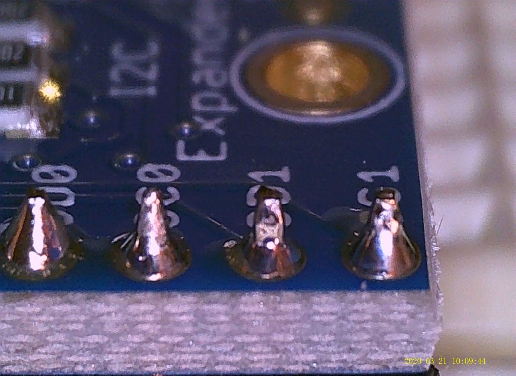
Maximum zoom, used to inspect four pins on the I2C Expander module.
For scale, these pins are spaced 2.54mm (0.1″) apart.
Near-minimum-zoom view of a UV-erasable EPROM chip.
This is a DIP28 600-mil package, so it’s roughly 15-16mm (0.6″) across.
Medium zoom, focusing on the near edge of the same EPROM chip
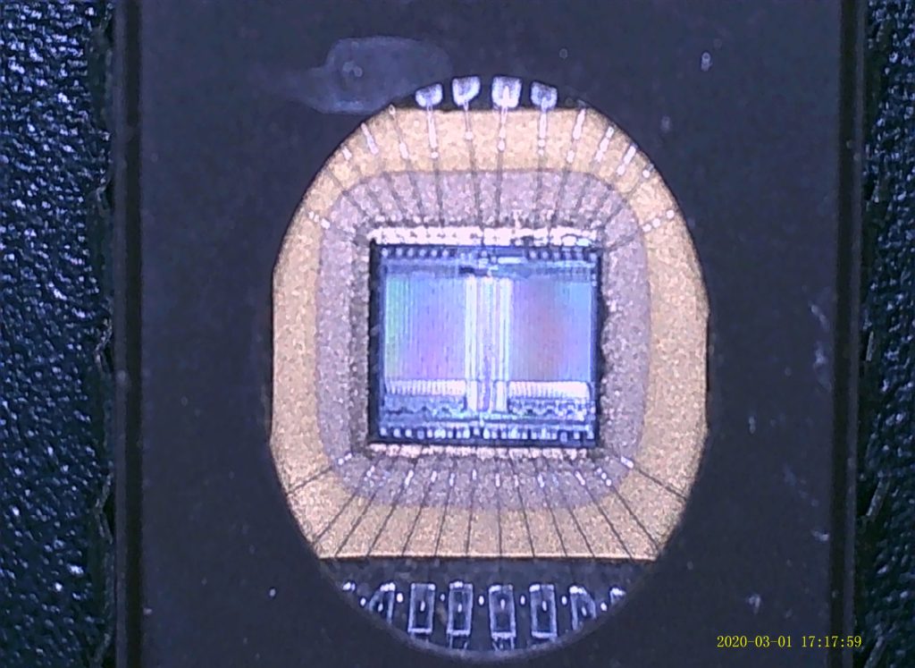
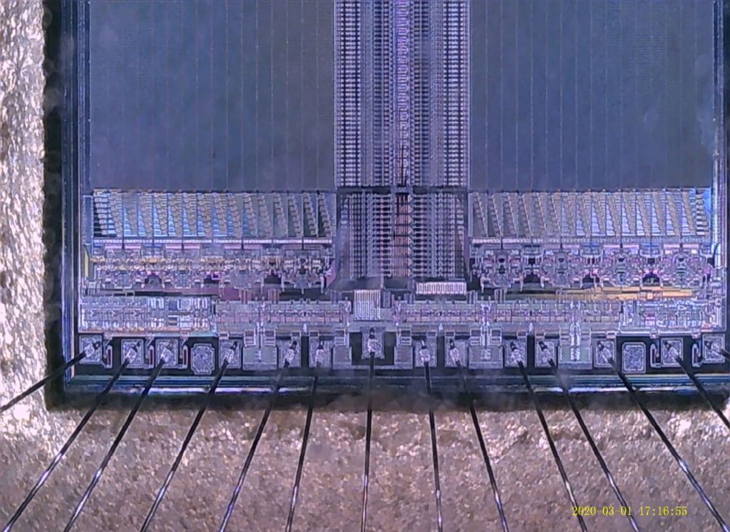
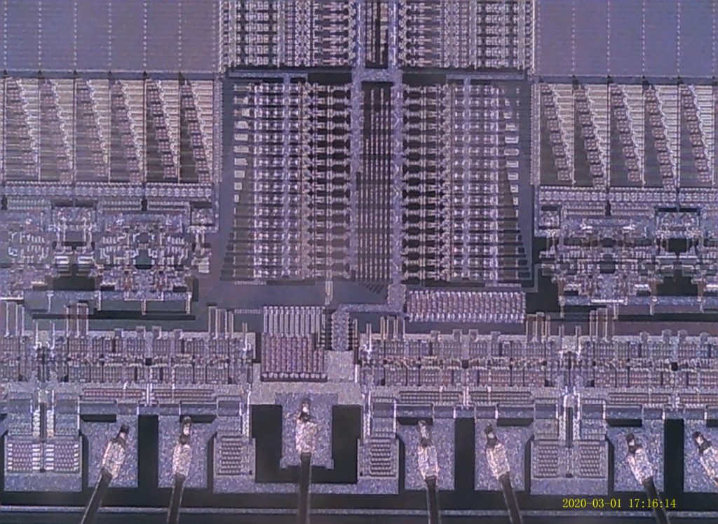
Maximum zoom into the same EPROM chip, showing the binding pads and interface circuitry.
You can almost see individual transistors, if still indistinctly.
(Click for original image for this and the others.)

It’s not very helpful for soldering — at least, not for 0.1″ pins — that goes much faster just looking at them the old-fashioned way. As it is, though, it’s certainly worth $65 or so for an excellent digital magnifying glass. It’s great for board inspections; you can clearly see all kinds of details that you’d miss even with a nice traditional magnifying glass.

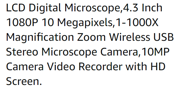
Just don’t believe all of the terms that they put in the product description. Here’s the truth:

  • LCD: Yes, it has a decent LCD display.
  • Digital: Check.
  • Microscope: Yes, if maybe not quite the 1000x zoom it claims. (See below.)
  • 4.3 inch: The display measures 110mm (~4.33″) diagonally (and uses it all). Check.
  • 1080p: No. It can do video over USB, but its maximum resolution is a (clear) 720p.
  • 10 Megapixels: It can produce 3840 x 2800, 24-bit .jpg files on the 10MP setting.
    So either it does take 10MP images, or at least it upsamples them to this.
  • 1-1000x magnification zoom: I was able to enlarge a pin measuring 580 microns
    across to roughly one foot across on my 45″ monitor.
    If you have a giant monitor, maybe 1000x??
  • Wireless: No. It’s “wireless” in that it has a Li-Ion battery, and
    can capture images and videos by itself. It needs a wired USB link for use with a PC.

    It doesn’t seem to have any kind of radio link like Wi-Fi, Bluetooth, etc.
  • USB: It can charge via Micro USB as well as act as a PC camera over USB.
    It can likely transfer pictures via USB, too. (So far, I’ve just used the MicroSD card.)
  • Stereo: This one boggles the mind. I think the video record feature also records audio.
    …Maybe they’re referring to this? It is NOT a stereo microscope. Not at this price.
  • Microscope: Yes; up to maybe 500x or so on a reasonably large monitor.
  • Camera: Yes.
  • 10MP: Maybe?
  • Camera video recorder: It does record video, although not at 10MP, of course.
  • with HD screen: Probably not. It’s probably 640×480 or something like that. It’s adequate.
The product description, from Amazon.

Bottom line: I’d buy it again. It’s useful enough, even if the claims are a little exaggerated.

Posted in Tools, Toys | Leave a comment

TTGO T-Display I2C pin location

You can’t always trust the datasheet.

The TTGO T-Display is a great little dev board, incorporating an ESP32 processor (with WiFi and Bluetooth support) and a small OLED display. With the header pins soldered on, it’s breadboardable — and even has a battery connector to use (and presumably charge) a small Lithium-Ion battery. Not bad for about $10.

Unfortunately, one effect of using such new technology is that the specifications sometimes change out from under you — and the firmware (let alone the documentation) takes a while to catch up. Production changes are made to solve problems, other changes are made that make these changes unnecessary, and then they’re reverted for only part of the system.

You’d think that something that breaks I2C would have been caught by now, though, especially when it’s a simple fix. Sometime in the development of the TTGO T-Display board (or a predecessor), an onboard LED was apparently placed on GPIO pin 22 (which serves as the SCL clock pin for I2C.) This LED was said to cause problems with I2C communications, so the solution was to remap SCL in the board definitions to pin 23 from pin 22.

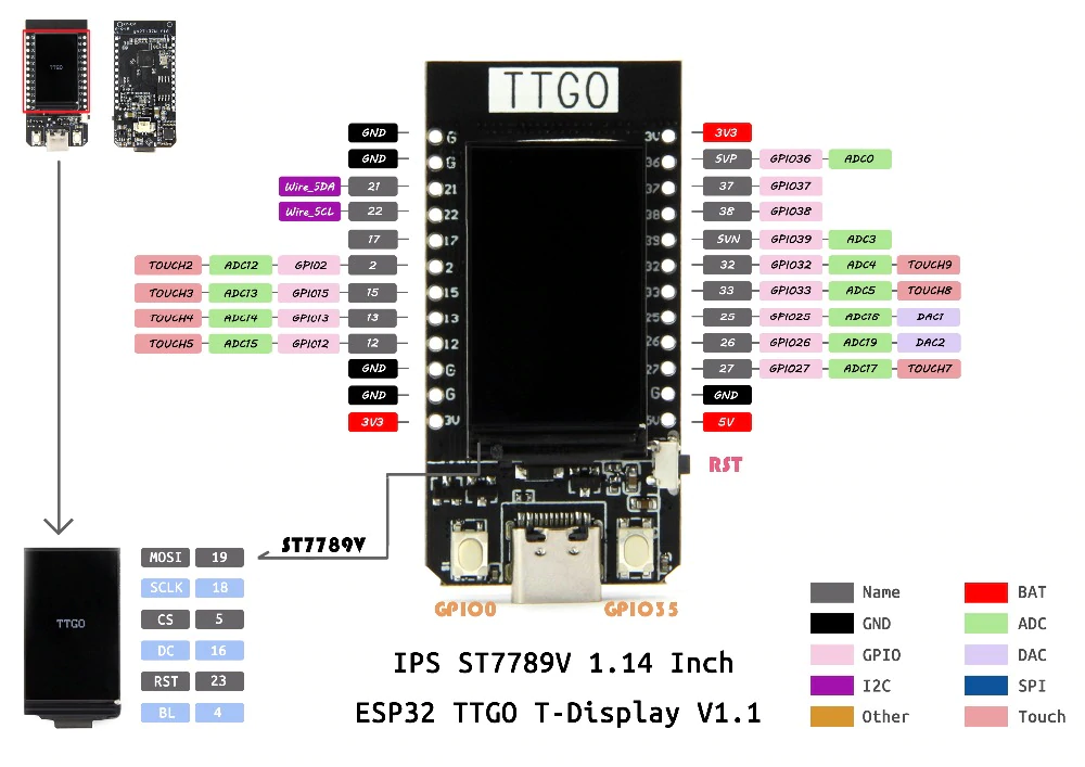
The TTGO T-Display pinout, according to LilyGo.
Unfortunately, Pin 22 isn’t SCL. That’s defined as Pin 23…
…which isn’t brought out to a header.

Great — except nobody ever updated the pinout — or bothered to bring Pin 23 out to the header. A pin intended to connect to external peripherals is useless if it isn’t brought out to a pin where you can get it to the breadboard or external device.

A quick “Blink” clone test convinced me that nothing blinks when Pin 22 is made an output and toggled high to low, so most likely whatever LED was associated with Pin 22 was deleted long ago. Trying out SoftWire (a software-based I2C implementation) on pins 21/23 worked fine, clearing the way to change it back.

A quick Google search led me to the location of the pin definitions file for the T-Display board:

C:\Users\<user>\AppData\Local\Arduino15\packages\
esp32\hardware\esp32\1.0.4\variants\ttgo-t1\pins_arduino.h

SDA and SCL are defined just a few lines into this file. Once SCL was changed back to 22, the built-in Wire library started working. If I2C doesn’t work on your TTGO T-Display, this is why. Make the change to the file listed in bold above, and it should work.

I’d submit a pull request, but I can’t figure out who’s responsible for maintaining the ESP32 variant in the Arduino libraries. Searching through the TTGO T-Display Github doesn’t pull up any references to the SCL pin (only SCLK).

Posted in Arduino, C, Coding, Digital, Troubleshooting | Leave a comment