For some reason, I’ve always really liked the idea of puzzle boxes. Being a Digital Design geek, I enjoy figuring out how systems work — and I think it’s just human nature to enjoy a good mystery.
Ever since reading about the (original) Reverse Geocache a few months ago, I had wanted to build one. Except for the box itself, I already had all of the pieces I needed (microcontroller, GPS, LCD, servo motor, battery) — and the microcontroller code to tie them together.
Traditional geocaching is a high-tech game of hide-and-seek, where you are given the latitude and longitude of a hidden container, and you use a GPS receiver to navigate there and find it. It’s a fun hobby, good exercise, and definitely recommended.
Reverse Geocaches were recently invented by Mikal Hart. (He created the original one as a wedding present for a friend — the story is a great read.) The idea is nothing short of genius — instead of finding a hidden box, give the box to the recipient, with no instructions. “Reverse Geocache” is his trademark, so I guess mine is a “GPS Puzzle Box.” (Heck, this lets me expand the idea with accelerometers, gyros, light sensors, etc later, anyway.)
The box (which is locked, with no readily apparent unlocking mechanism) has an LCD display and a single button on its top. Pressing the button, once the box is where it can get a GPS fix, results in a distance (say, in km) being displayed on the LCD. The box “knows” where it wants to go, and will only open when it is at that particular location.
My wife’s birthday was coming up, so I decided to build one for her while they were still a unique gift. (Despite the best intentions of its inventor, I’d be surprised if we didn’t see these in Wal-Mart in a few years’ time. They’re just that cool.) My wife is inquisitive and very bright — but she can also be very impatient and is not by any means a “gamer” — so I wasn’t sure how things would turn out.
Here is a relatively detailed look at what is involved in making a project like this. (If you’re thinking of getting into microcontroller electronics yourself, you definitely should — it’s a lot of fun, not too hard to learn, and doesn’t cost anywhere near as much as you might think.)
First, I prototyped the design on solderless breadboard. This is a great way to start out a new design, since it allows changes in the circuit to be quickly made. It also makes diagnosis easy, since portions of the circuit can be easily disconnected and tested independently from the rest.
Here is the schematic for the device. A reed relay was used to control power to the peripherals; in standby mode, only the PIC draws power, waiting for the button to be pressed. In this mode, the I/O ports are tristated, and the onboard oscillator is run at 31kHz instead of the usual 8MHz.
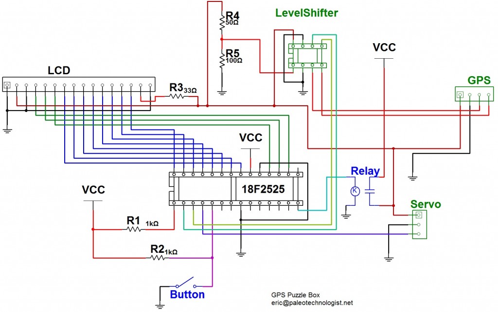
The schematic. Most components are powered off in standby mode; accessory power is controlled via the reed relay. Click for larger.
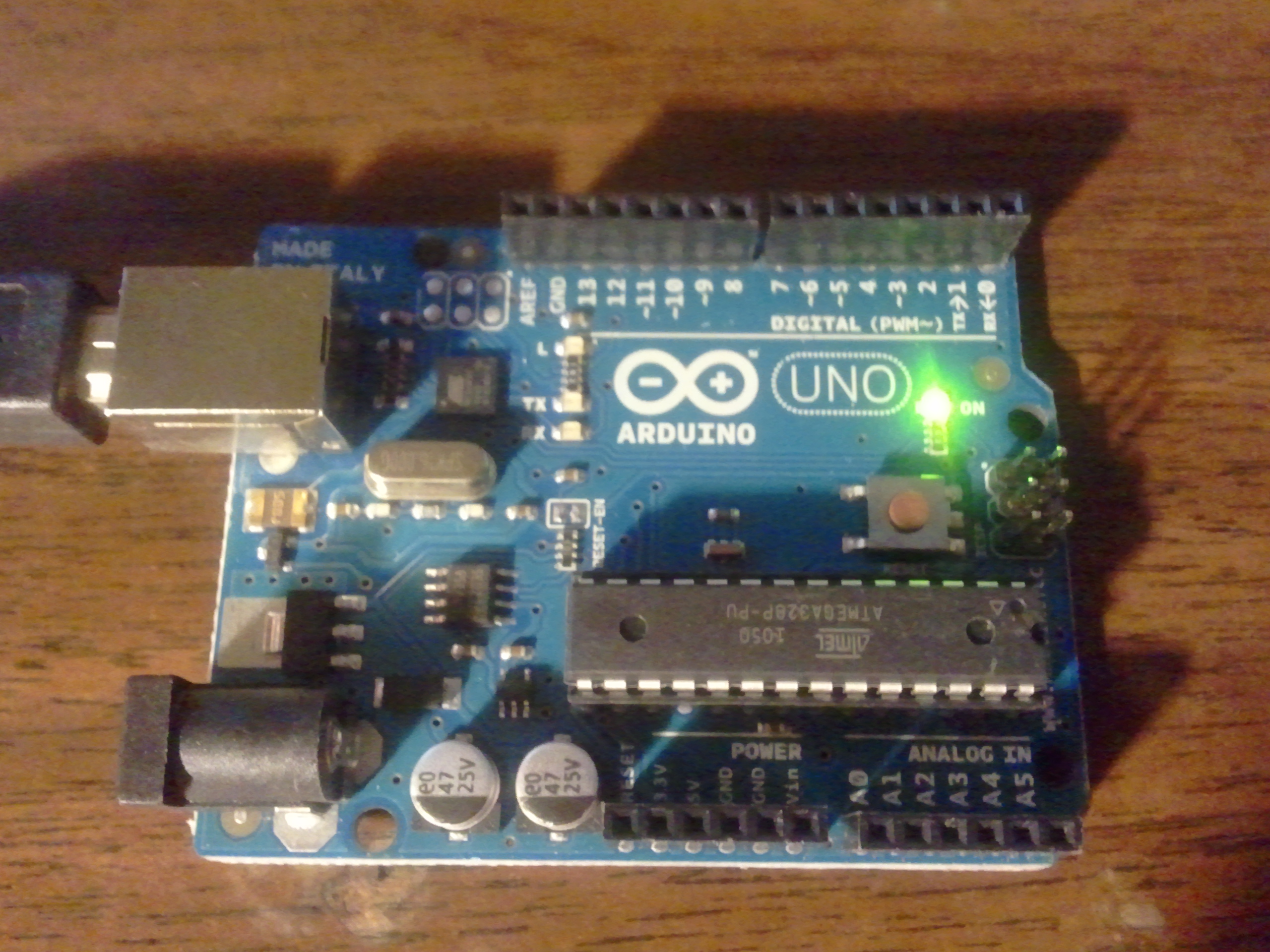
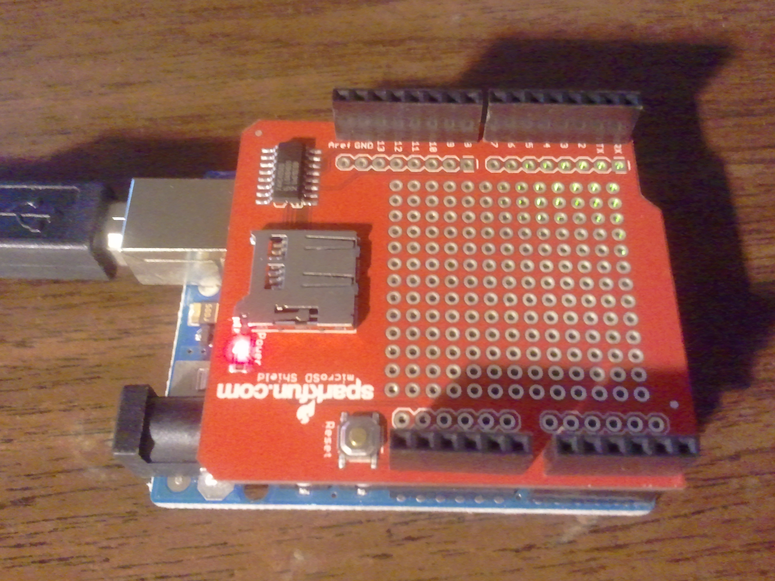
Although due to the nature of the device, large pieces of the design certainly resemble Hart’s original, I designed the box from scratch, going just from Hart’s idea of a locked box with a GPS, an LCD and a pushbutton. The original used an Arduino, but since I’m pretty much a PIC partisan, I went with a PIC18F2525-I/P microcontroller. (Dev boards like the Arduino are cool, especially if they get more people interested in prototyping — but it just seems wasteful to use a whole dev board in a project when a bare MCU will do. Each part in the design does something, this way. Besides, it’s cheaper.)
Given that the box had to not only handle operating a LCD and servo, but do GPS position (distance) calculations, I decided to program the firmware in C. (My reasoning was that rewriting my LCD and servo code in C would be easier than doing a floating-point implementation of square root in assembly. Even I’m not that fanatic — yet.)
Writing the LCD code was fairly straightforward; there are some timing constraints, but all of these are of the easily-resolved “not less than” variety. You could send commands to the LCD at a rate of one bit per century, and it should work just fine.
Once the LCD code was sorted out (this way, I can use printf() messages for debugging), I moved on to the servo code. This was trickier, but still fairly straightforward; with the use of a ‘scope, I could tell if the pulses were more or less the right length, and could then tweak them to make the particular servo used turn to the right angles. (Servos do vary in timing among individual units, but each unit seems reasonably consistent over time, fortunately.)
The most difficult part of the project was getting the GPS and serial code working. Without the LCD to help debug, this would have been impossible. To make a long story short, since I was running the PIC on its internal 8MHz clock, the timing was only guaranteed to within 2% or so, which turned out to be too imprecise to run the 4800 baud serial timing at spec. Instead, I had to tweak the per-bit and per-half-bit timings to make everything come out as it should — and the settings for this vary with the individual PIC used. I really ought to have included a TTL oscillator, but the PIC’s onboard oscillator turned out to be stable enough that I could tweak it into working. (Digital storage ‘scopes which can grab a frame of NMEA output and let you zoom in, checking timings and output sequences, are a wonderful invention, by the way.)
Now I had to find a suitable box. A quick eBay search turned up a broken music box that looked perfect.
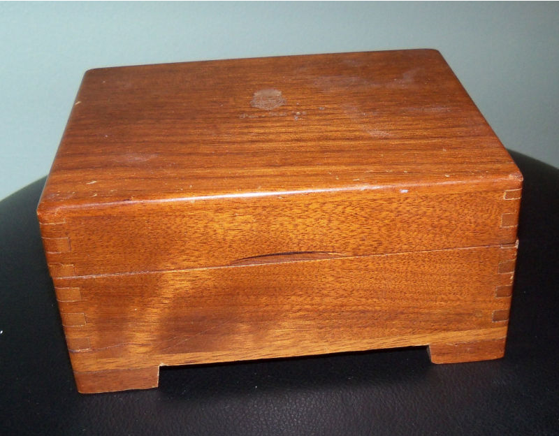
The box, prior to being repurposed
Once the box arrived, I looked it over; the mainspring in the music clockwork had broken, so I didn’t feel as bad about repurposing it. (I kept the music clockwork in my parts bin anyway — I could always drive it with a motor or something.)
Next, I had to decide on a layout for the components, which meant deciding what batteries to use. I measured the current for the whole setup, and came up with about 80mA running, and very little current when dormant. At 850mAh capacity, four rechargeable NiMH AAA batteries would provide about ten hours’ runtime, which would be plenty. With the GPS, LCD, and button in the recessed lid, I decided to put the batteries and circuit there, too (to avoid running a dozen or so wires to the base.) This left only a few wires to run to the base, for the servo and debug lines.
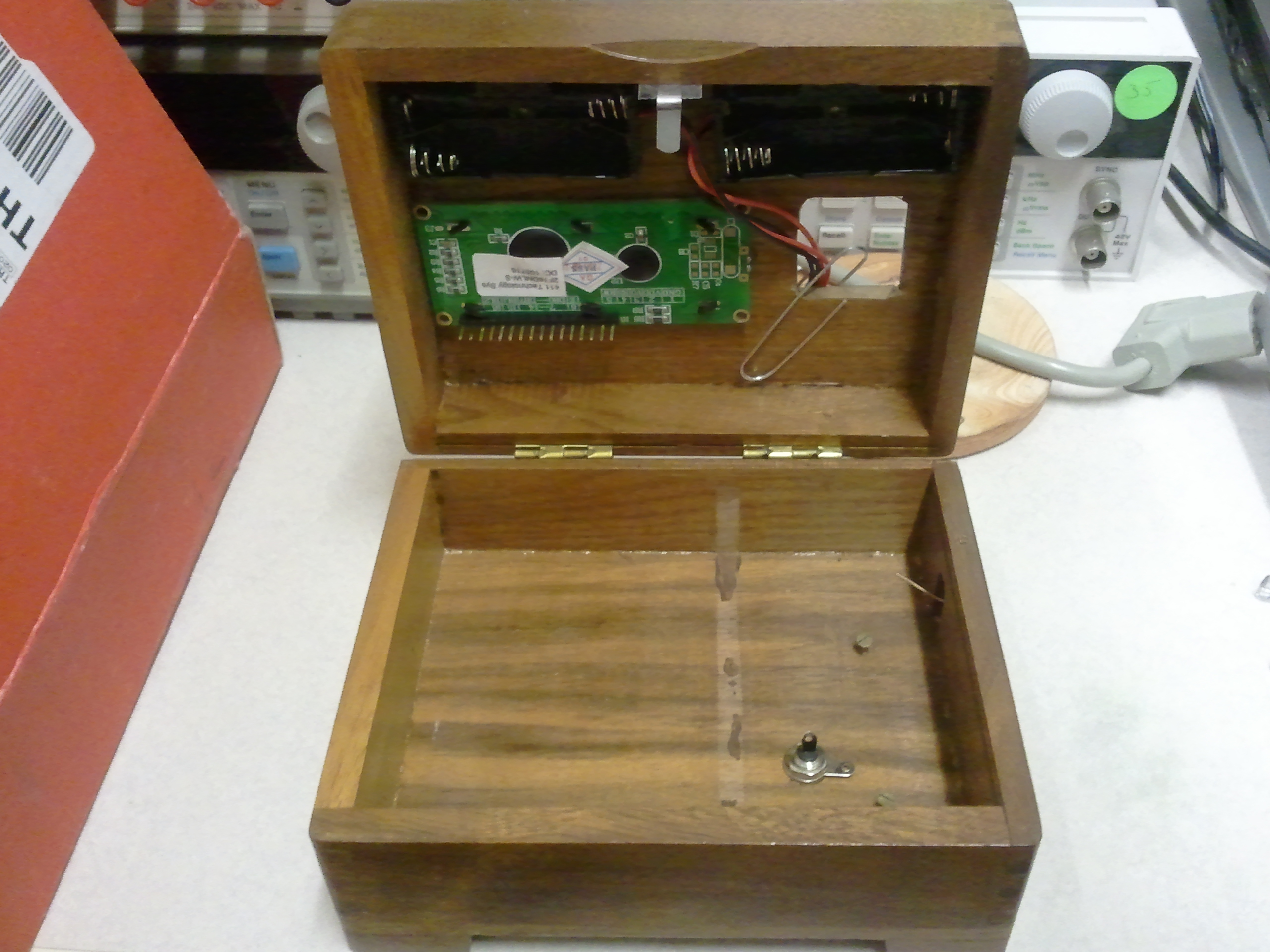
The batteries, LCD, and opening for the GPS. (The circuit board clips on to the bottom of the LCD.)
Once the LCD and GPS openings were in place, I went about designing a locking mechanism. The local Target had a picture-hanging kit, from which I was able to bend a few metal hooks into latches. Mikal Hart’s design uses a cut chopstick as a latching mechanism, but I figured I could get away with using a servo horn directly, if it was supported solidly enough.
The next step was to move the circuit from the breadboard to a circuit board. I cut a Radio Shack circuit board to fit, then figured out where the LCD header needed to go. From there, I laid out the sockets for the PIC microcontroller, as well as the relay and other various parts.
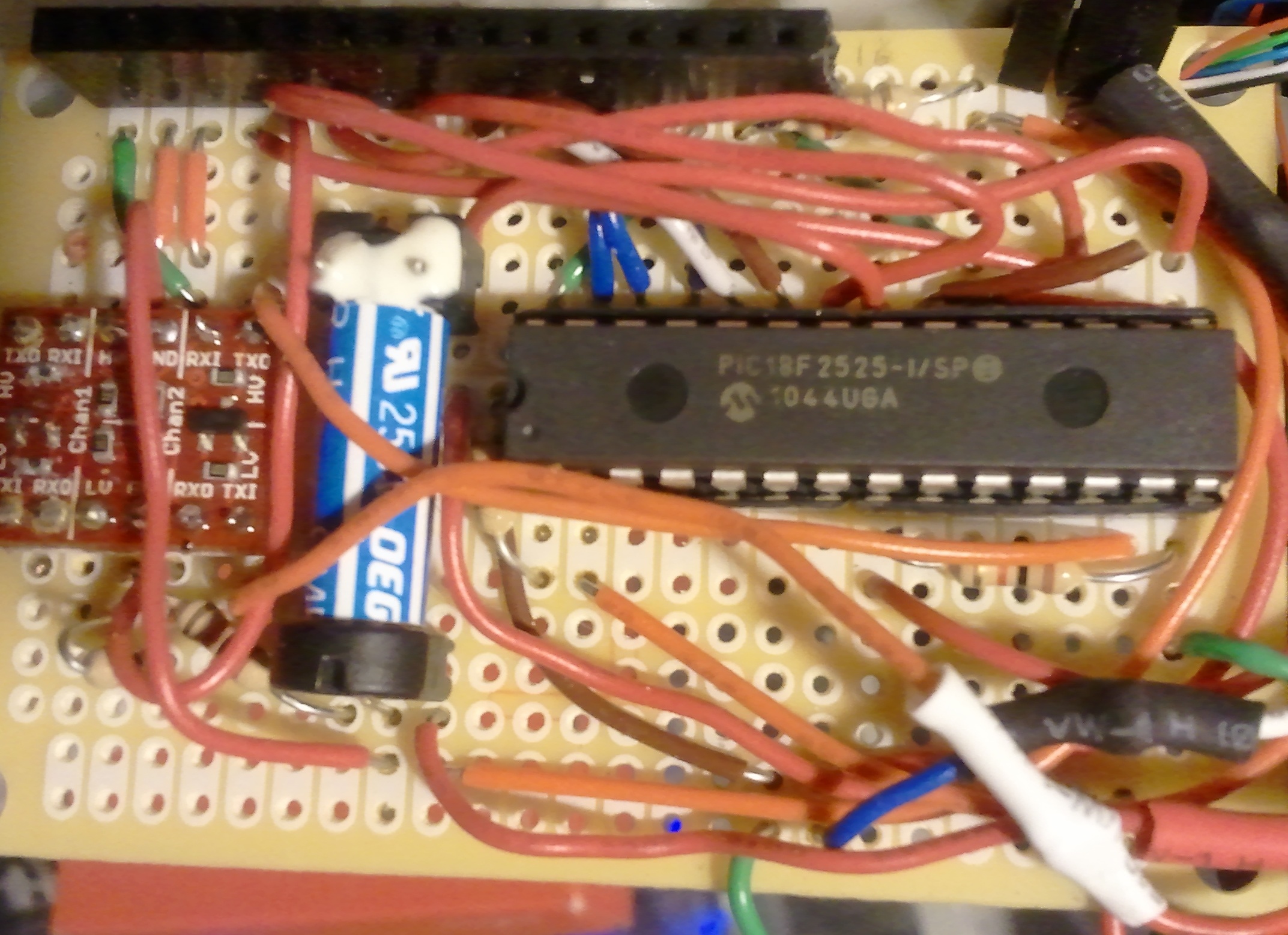
The circuit board. Not very pretty, but functional.
Once the circuit board was built, I tested it, keeping the lid open. Everything seemed to work correctly, but to help Murphy’s-law-proof the device, I created two backdoors. First, I brought out all five debugging pins (Vcc, Ground, Vpp, PGD, and PGC) to a wire-wrap header tucked discreetly underneath the box. Next, I put a check in the startup code to unlock the box if the button were held down at power-up.
With these precautions in place, I finally shut the box for full-scale field testing. Apart from some “urban canyon” GPS problems, it worked well on a quick walk to a nearby restaurant; the distances decreased as I walked towards the designated coordinates, and the box opened once I got there.
Next, I decided to test the practicality of using a map to determine the goal location. I picked a goal location near where I lived, then drove home from work, checking the location on occasion when stopped at traffic lights.
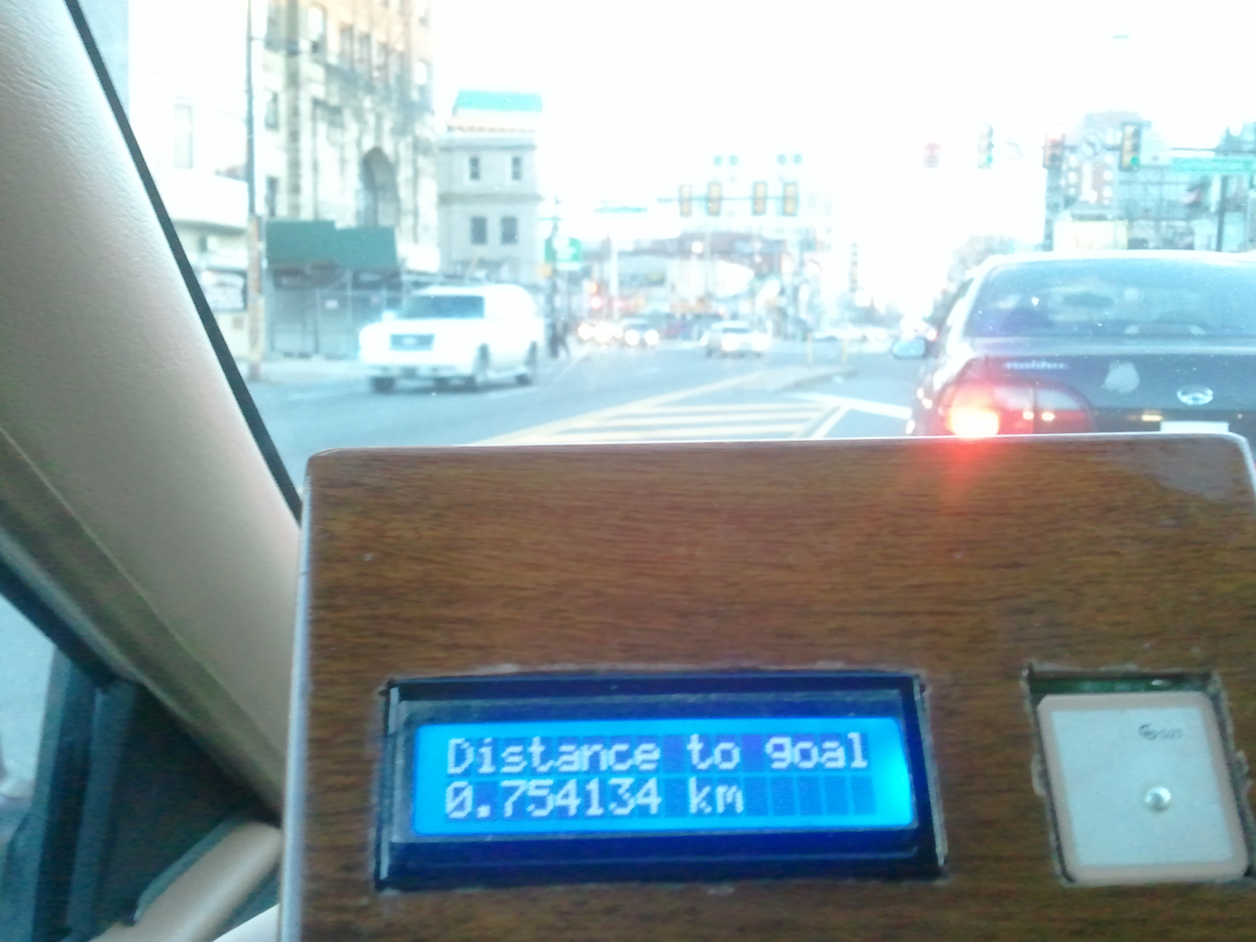
The GPS Puzzle Box in action!
The box dutifully opened once I got home — but how accurately would the various distances recorded allow me to determine the goal, if I didn’t know it in advance? I entered the corresponding circles into MapPoint, and got the result I was looking for — intersecting arcs well within half a block of the goal. The box really worked — and just in time: my wife’s birthday was that weekend. I prototyped a hollow block of ABS plastic with an inscription (it helps keep the wires under control), and covered up the electronics with a piece of green construction paper.
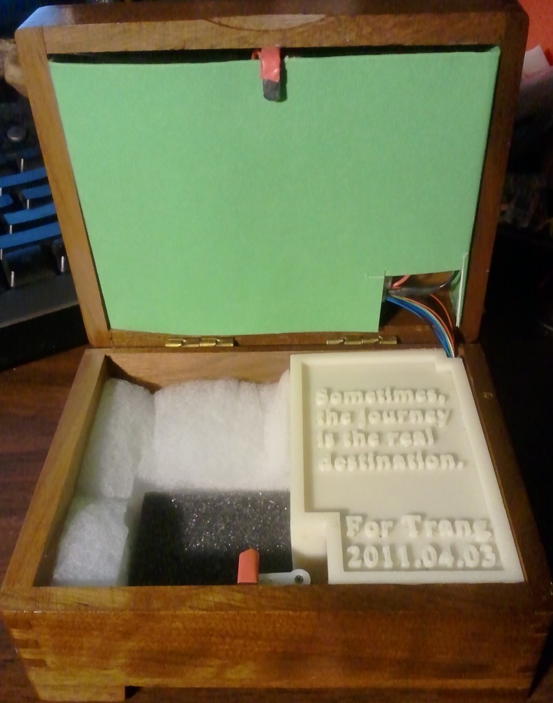
Inside the finished puzzle box. The latches are bent picture hangers, covered with shrink wrap. The servo horn can be seen at the bottom (it's in the closed position here "locking" the box open.)
Finally, it was showtime. I reset the box, loaded it with some nice opal-and-silver jewelry (I’m not totally clueless!), and set the destination for the parking lot of Longwood Gardens.
How did my wife react? Well, the “practical” / “impatient” side almost won out. Once she determined that the box wasn’t going to open right then and there, she discussed encouraging it to open using a screwdriver and/or a hammer. (Like I said, she’s very practical that way.) I convinced her to give solving the puzzle a try, though, and we set off (laptop and PICKIT2 debugger along just in case).
“Which way should we go,” she asked. I shrugged and said the box just seemed to give a distance, not a direction. She decided that it might be somewhere west (statistically, a good guess; we go that way a lot), so we set off down I-76. The distances started decreasing, so we were on the right track.
Her next question was “How do we know which way to turn?” I tried turning things around on her. With several degrees including an MD, she’s easily smart enough to know how to solve this puzzle, but needed to get past her impatience. “Where are all the places 48.2km from here,” I asked. “Well, they’re in a circle.” She had the right idea, but was still fiddling with the hinges and talking about cracking the box open.
We stopped for breakfast and I got out my laptop to show her the first two distance circle intersections on the map. One was to the northwest; the other to the southwest. She picked the first one (also statistically a good guess, which happened to be wrong this time), and asked how we would know if that was it. I showed her how a third circle would answer the question — or if the distance started increasing once we turned north, that would also mean we had gone the wrong way.
We turned north, and soon the distances did start going up. At the next exit, we stopped for fuel and turned around, following 476 south. Eventually, the distances started decreasing slowly; the intersection had indicated the goal was west of 476, so we turned west. A short while later, she guessed the destination (there were signs along the way.)
Once we got to the parking lot, the box opened. Seeing the jewelry definitely improved her opinion of the whole adventure — and we had a pleasant day walking around Longwood, as well.


