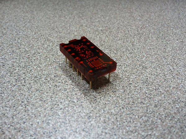
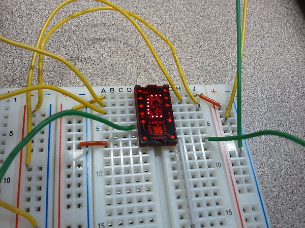
Back in the day, when men were men and computers were programmed in hexadecimal, Texas Instruments produced a nifty little display chip called a TIL311. This chip took a 4-bit nibble as input, and produced a single hex digit on a built-in LED display. As if that weren’t cool enough, TI packaged it in translucent red; you could almost convince yourself that you saw the electrons moving through the traces as the display digits changed. This wasn’t a consumer-oriented BCD display for use in calculators and clock radios (though it would work nicely for that) — this was an actual hexadecimal display, capable of displaying numbers beyond zero-through-nine.
To paraphrase This Is Spinal Tap, “these went to fifteen!”
Unfortunately, although they’re still as useful as ever, TIL311s are extremely scarce today. The best price I could find online was $19.95 apiece. (For comparison, you could get several backlit 32-character LCD displays for the same cost.)
For Drexel’s EET325 Microprocessors class this term, we wanted to capture the essence of programming a vintage 8-bit CPU like the Z80. A modern LCD display would be simpler to implement, but somehow it just wouldn’t be the same. Hex displays like the TIL311 worked beautifully: one hex digit exactly covers four bits. Two digits cover one byte (for the data bus) and four cover a 16-bit word (for the full address bus on the Z80). The most recent versions of the DrACo/Z80 are true 8-bit machines, though: the address bus is 8 bits wide (although expandable to 16). Because of this, only four hex digits are needed; two for the address and two for the data.
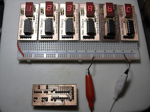
Even so, four TIL311s per board would add $80 to the bill of materials — roughly doubling the cost. This, we figured, was an opportunity to put our LPKF PCB plotter to use creating some modern TIL311 replacements. A PIC16F1825 microcontroller, a common-anode seven-segment LED display, and seven resistors take the place of TI’s slick one-chip solution. It isn’t nearly as pretty, but it gets the job done for a bit less money.
A few design revisions and squashed bugs later, the first of the new boards are up and running. The PIC runs in a continuous loop, monitoring the four data pins and updating the seven-segment output based on data in a lookup table. (The code is easily converted to a common-cathode design by inverting the display bits; the board would have to be modified to support this. It would have been nice to be able to do this in software by using an I/O pin as a switchable common, but unfortunately there were no spare pins left.)
Here is the zipped PIC project to reproduce this display for yourself, along with the layout file used to create the board layout in FreePCB. The design is completely single-layer for ease of soldering, although if using double-sided copper-clad boards like we did, the holes on the top layer must be insulated. The PIC actually runs at its slowest self-clocked speed of about 31kHz; since the monitor-lookup-and-update loop only takes 36 cycles, the display can still be updated at several hundred Hz — fast enough to be a blur if the Z80 is running that fast. (The design should work at any speed, since no timing at all is used; the PIC is simply emulating combinatorial logic as fast as possible/necessary.)
Some details on construction: All resistors are 470 ohm, although any similar value should work OK. The connector is a standard 0.1″ row connector, with the plastic insulator pressed all the way to one side. This way, the connector can be inserted through the top of the board, soldered to the bottom side like all of the other components, and have enough pin length left to comfortably fit into a solderless breadboard. Since these boards will be used in a classroom lab setting, I opted to socket the PIC. That way, if one accidentally gets its power reversed and/or is introduced to 12V instead of 5V, we can easily replace it.
Since the LED display is driven by the PIC, it is less likely to be damaged due to incorrect connections; the PIC is unlikely to pass enough current to it to cause damage. The LED is keyed, and will only go in one way. (Yes, it’s supposed to be upside-down; these boards don’t use the decimal point, and the circuit layout worked much better that way.)
I’m still working on refining the parameters for producing boards on the LPKF plotter (not to mention dealing with some persistent alignment issues) — but it’s definitely getting there.
If you decide to make one of these for yourself and have questions, please email me (“Eric” at this domain); I’ll be happy to help.


