Sugru

While ordering the latest batch of toys components from SparkFun, I noticed something new — a 12-pack of moldable, air-curable rubber called Sugru. The description said that it could be used for all kinds of hacks, repairs, and inventions. It looked interesting, so I picked up a pack to try out.

The Sugru sample pack.


Opening the pack, I found twelve packets in various colors, two sets of Sugru stickers, and a mini instruction manual.

The contents of the Sugru sample pack. (Click for larger.)


Opening up a blue packet, I found the Sugru material quite a bit tackier than I’d expected. It’s like a mix of modeling clay and Silly Putty, and seems to want to stick to everything.

Sugru in its native habitat. Now I know why they recommend cutting through three sides of the package to get at it. (Click for larger.)

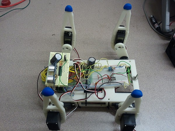
I initially tried making a D4 (tetrahedron), but wasn’t able to form the shape accurately, since the Sugru stuck to the desk. (It sticks to everything.) I then split it into four pieces and formed “feet” for the SIGMA walking robot.

The robot with its feet in the air, waiting for the Sugru to cure. (Click for larger.)

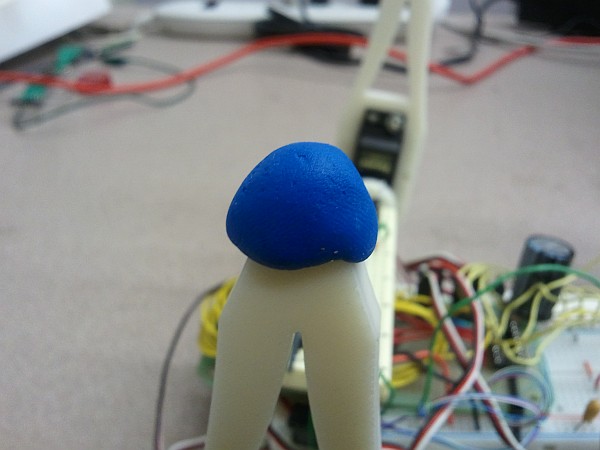
A closeup of one of the robot's new Sugru feet. (Click for larger.)

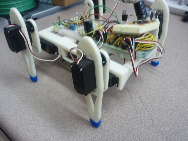
A couple of days later, the Sugru had cured nicely into a rubbery form, and the robot was ready to try out its new shoes.

The SIGMA robot's new Sugru shoes. (Click for larger.)

I’m still figuring out what I’ll use Sugru for, but it does seem to work well for various types of small mechanical hacks — basically, any place you’d like to be able to put Silly Putty and have it cure into a waterproof rubber-like substance over a day or two.

Posted in Design, Reviews | Leave a comment

Oscilloscope Basics

Working with electricity can let you do some amazing things — like move objects around, produce, record, play back, and analyze signals of all kinds including audio and video, and even build computers and computer networks.

Unfortunately, electricity is not only useful, but invisible — which can make it difficult to see exactly what is going on in a circuit.

This is where oscilloscopes come in. An oscilloscope is a device which translates an electrical signal into an onscreen plot — usually, of voltage vs. time. The X (horizontal) axis generally represents time (increasing left-to-right), and the Y (vertical) axis generally represents voltage. Both of these can be scaled appropriately to show the features of the signal that you’re interested in.
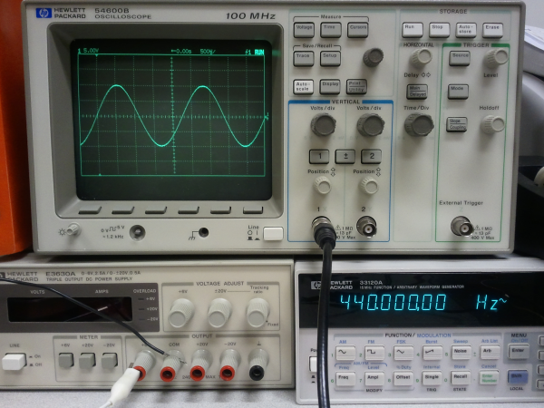
An oscilloscope, displaying a 440Hz sine wave from a signal generator. (Click for larger.)

There are many controls on a typical oscilloscope — which can make learning oscilloscope use somewhat intimidating, at first. Here are a few tips to help get you started:

  • It’s (almost) impossible to damage the oscilloscope by setting the controls wrong. The worst that would generally happen is to set the ‘scope to settings that don’t make sense for displaying the signal you’re looking at. (This is assuming that the signal being fed into the oscilloscope is of a reasonable voltage.)
  • There are four basic controls that you should become familiar with:
    • The “Time/Div” control, which determines the speed of the sweep. Turn this knob clockwise to display faster signals (less time per horizontal division on the screen); turn it counterclockwise to display slower signals (more time per division on the screen.)
    • The “Delay” control. This basically moves the display left and right, allowing you to see other parts of the signal. It has more functionality on a digital ‘scope because of differences in the way these ‘scopes work. (I plan on writing an article about the differences between digital and analog ‘scopes someday.) For now, think of this as a “pan” control which lets you view earlier or later parts of the signal on the screen.
    • The “Volts/Div” control. This sets the vertical scale of the display. Turn this knob clockwise to display small-amplitude signals (fewer volts per vertical division on the screen); turn it counterclockwise to display large-amplitude signals (more volts per vertical division on the screen.) Remember that many oscilloscope probes include a voltage divider — typically 10:1 — and that this can make the displayed voltages appear smaller than they are, if the ‘scope doesn’t compensate for this.
    • The “Vertical Position” control. This allows you to move the display up and down, centering the display on a higher or lower voltage. For instance, if you wanted to analyze a 1-volt sine wave that had a 3-volt DC bias, centering the display on +3 volts would allow you to increase the vertical gain and see smaller details of the signal.
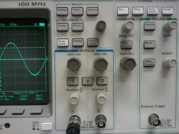
The controls of an HP 54600B digital oscilloscope. (Click for larger.)

Modern oscilloscopes have many other controls — including various trigger modes (the trigger function determines when the ‘scope starts drawing the plot across the screen); coupling modes (AC coupling inserts a series capacitance, removing DC bias from incoming signals); and many others, such as bandwidth limiting (for filtering out high-frequency noise).

One major benefit of modern digital oscilloscopes is the “Auto Scale” function (the white button just to the right of the screen on this ‘scope.) This “magic button” analyzes the incoming signals and makes an educated guess as to what display settings would work well. I find that it guesses right about 3/4 of the time — and the rest of the time, it usually focuses on one particular part of the signal — perhaps a noisy transition such as ringing noise on a square wave.

Also remember: “When in doubt, zoom out.” Set Volts/Div to a fairly high level (counterclockwise) and Time/Div to a slow speed (also counterclockwise). This will generally let you see the “big picture” and then zoom in as needed. Don’t overdo the Time/Div, though — at several seconds per division, it might seem like the ‘scope has stopped responding when it takes the better part of a minute to trace across the screen one time!
Posted in Analog, Digital, EET205, EET325, Electronics, Fundamentals, HOW-TO, Tools | 2 Comments

Vector Boards (old-school prototyping)


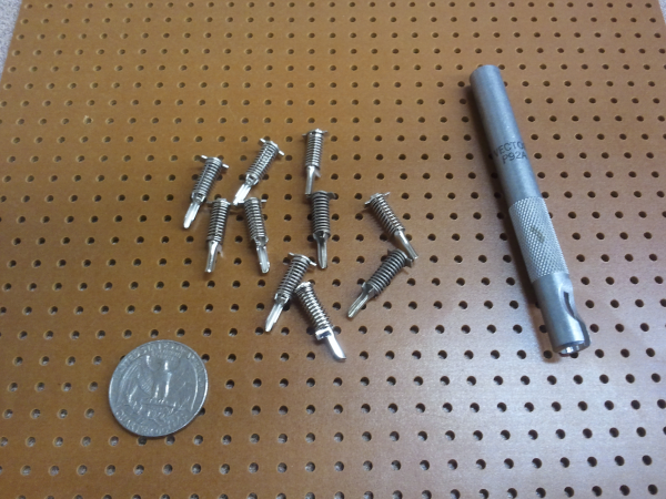
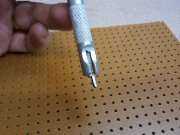
An older alternative to breadboarding is vector board. Prototyping with vector board involves inserting specialized “vector springs” into a board with pre-drilled holes. A pin insertion tool is used to insert the springs as well as to open them up to insert wires and/or component leads.

Vector board, pins, and insertion tool. (Click for larger.)

The first step is to use the tool to insert the pins. These are not easily turned once inserted, so it’s important to align them the way you want (or allow extra lead length).

A vector pin in the insertion tool. (Click for larger.)

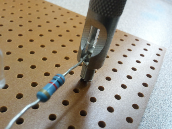
Once the pins are inserted, the tool is turned 90 degrees to press down on the spring and open the pin up so wires or leads can be inserted.

Using the insertion tool turned 90 degrees to compress the pin for component insertion. (Click for larger.)

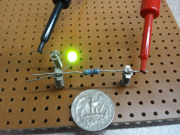
The rest of the circuit is constructed this way. It can be tricky to get both ends of a component seated using only one vector tool, since only one pin can be easily opened at a time. (A fingernail or screwdriver could be used, in a pinch.)

A simple circuit, built using vector board. (Click for larger.)

Overall, I can see why vector boarding isn’t popular these days — it’s quite a bit more time-consuming to build circuits this way, compared to using solderless breadboards. The circuits, once constructed, seem to be nearly as robust as if wire-wrap had been used, and a bit more reliable than breadboarded circuits.

Posted in Electronics, Nostalgia | Leave a comment

Bah Humbuck

Recently, I stumbled across a basic $25 electric bass in Goodwill and bought it to see what it was like. I brought it with me to visit my folks; one thing led to another and they offered to get me a much nicer Ibanez as a graduation present. I’ve been enjoying studying bass-playing techniques, but as an electronics enthusiast, I find the construction details as interesting as the musical aspects of the instrument.

When you determine the frequency range of an electric bass, for instance, you find that it covers the 60Hz US household AC power frequency. (If 60Hz were a note, it would be almost exactly halfway between A#1 and B1. Incidentally, it would also be a very precisely-played note.) For an EE type — even a Digital specialist like me — that brings up an important question. How do you filter out the 60Hz influence, when that frequency is solidly in the range of frequencies you’re interested in preserving? You can’t really use standard filtering techniques like a notch filter — in order to cut the 60Hz by 20dB or so, while not appreciably chopping the two notes on either side of it, you’d need to have a cutoff curve of something like 240dB/octave, which would be difficult to say the least.

So, how do they do it? DSP? Use super-heavy shielding for the electronics and keep the (metal) strings away from 60Hz influences? As it turns out, there’s a simpler solution — humbucking.

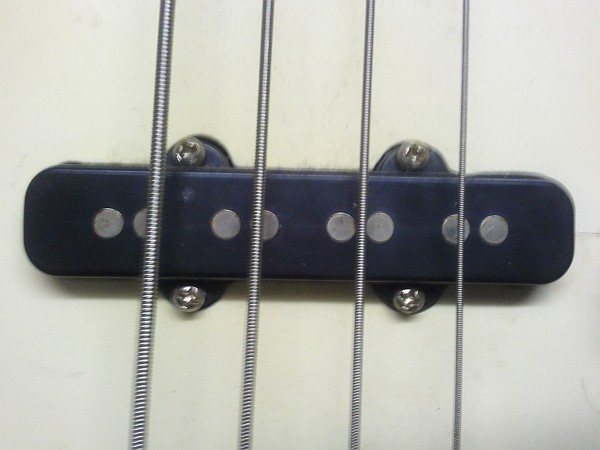
Humbucking relies on the use of two pickup coils per string. These are connected in series,  with one coil placed in the opposite direction from the other. This geometry causes any electric field crossing both coils to be more or less canceled out: 60Hz noise from nearby AC-powered equipment will induce an in-phase current in one coil and an out-of-phase component in the other. Since the two coils are in series, these two induced currents will (nearly) cancel, greatly reducing the amount of 60Hz noise picked up by the instrument.

Doubled (humbucker) pickups on an inexpensive bass guitar. (Click for larger.)

…Now if only there were a similarly elegant solution to help learn how to play the thing!


Posted in Analog, Audio, Electronics, Music, Toys | Leave a comment