One of the fastest, easiest ways to prototype a new design is by using a solderless breadboard. These accept through-hole devices and allow fast, reasonably secure connection of components with a minimum of wiring. An idea for a new circuit can be tried out in minutes instead of hours — and changes to the circuit can be made easily.
Solderless breadboards work by providing many holes containing electrical contacts, arranged in various useful connectivity patterns. These holes follow 0.1″ spacing (2.54mm in real units), and come in a variety of subtly-different configurations. The common theme is several dozen columns of connected holes, with a 0.3″ (7.62mm) gap in between. This allows for the use of 300-mil DIP components on the breadboard. (600-mil DIP parts can be used, as well, although they cover several rows of holes.)
Connection diagrams for three of the most common types are shown below:
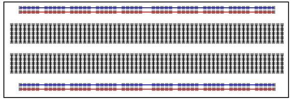
A typical 830-hole solderless breadboard, such as those sold by MPJA (Click for larger.)
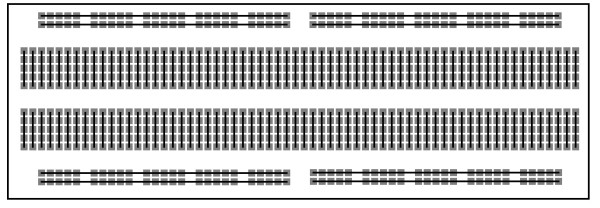
A "split dual rail" solderless breadboard. (Click for larger.)
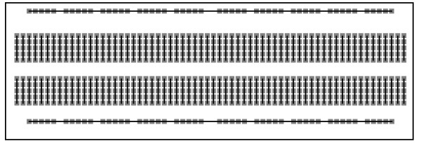
A single-rail type solderless breadboard. (Click for larger.)
Here is a walkthrough of a simple introductory project (a blinking LED) using a solderless breadboard. Total component cost is about US$10.
I’ve provided links to sources for the components — but all of these can be found from many different vendors. MPJA does have good prices for the breadboard and wiring kit.
Materials needed:
(1) solderless breadboard (almost any type will do for this circuit)
(1) breadboard wiring kit
(1) LED (any color)
(1) 555 timer IC
(1) resistor kit, containing:
(1) 470-ohm resistor
(1) 1k resistor
(1) 6.8k resistor
(1) 100uF capactor
(1) 0.1uF capacitor
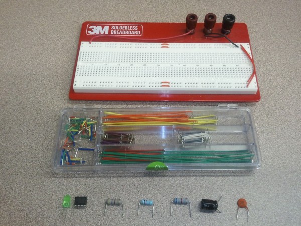
The parts needed for the 555 timer blinker project. (Click for larger.)
The circuit we will be building is an “astable oscillator,” using the venerable (read, “so cheap, ubiquitous, easy-to-use, and reliable that it’s still very popular despite its age”) 555 timer IC. The IC allows C1 (100uF in this example) to charge from +5V via both resistors until it reaches 2/3 of Vcc, then discharges it through R2 (6.8k) until it reaches 1/3 of Vcc. This action provides a regular timing function, which is converted into a TTL rectangular-wave output by the 555. A 470-ohm resistor is used to limit current to an LED, which blinks at about 1Hz (that is, about once per second.) Changing the values of the resistors and/or C1 would change the blinking frequency. For instance, if a 50uF capacitor were used instead of a 100uF one, the LED would blink twice as quickly.
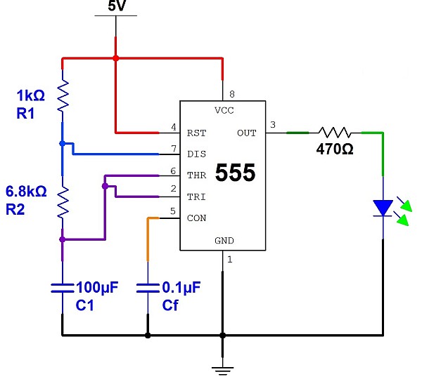
The schematic for a (roughly) 1Hz blinker, based on a 555 timer. (Click for larger.)
Procedure:
* Place the 555 on the board, straddling the center divide as shown. The 555 should be oriented so that the notch or dot identifying Pin 1 is on the left.
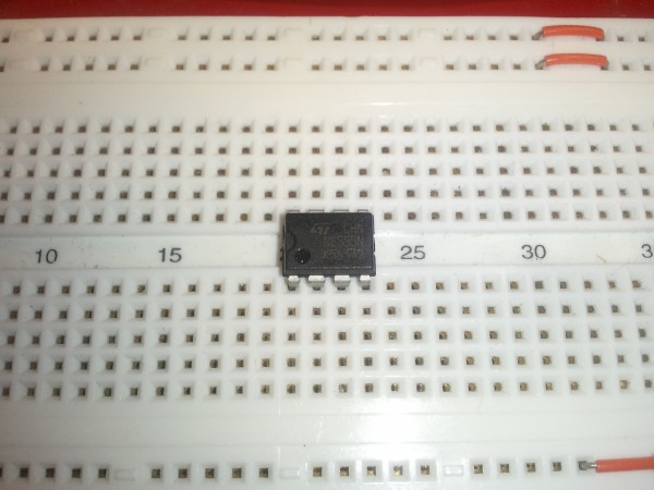
The 555 in position on the breadboard. (Click for larger.)
* Use a series of jumpers to connect pins 2 and 6 of the 555, as shown. (Pins on DIP components are numbered counter-clockwise from lower left, so Pin 2 is the second pin from the left on the bottom row, and Pin 6 is the second pin from the right on the upper row.)
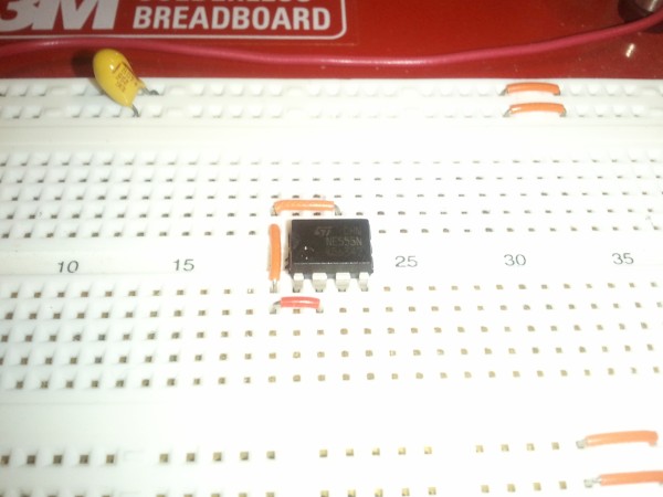
Using three jumper wires to connect pins 2 and 6. (Click for larger.)
* Place the 0.1uF capacitor on the board as shown, including its jumper wires. Polarity doesn’t matter if you are using a ceramic capacitor.
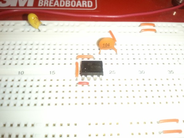
Connecting the 0.1uF ceramic capacitor between Pin 5 and Ground. (Click for larger.)
* Place the 100uF capacitor on the board as shown, including its jumper wires. (Remember to check the polarity; the negative side should go to Ground.
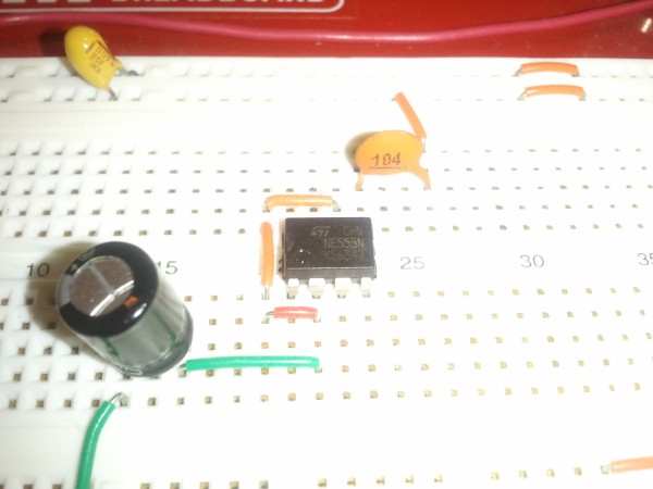
The 100uF timing capacitor connected between Pin 2 and Ground. (Click for larger.)
* Place the two timing resistors (1k and 6.8k) on the board as shown, including a jumper connecting the end of the 6.8k resistor to pins 2 and 6.
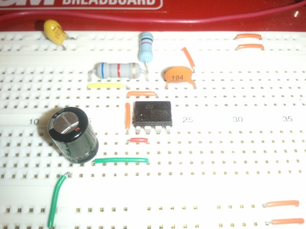
Connecting the two timing resistors. Don't forget the jumper wire from the far (left) side of the 6.8k resistor. (Click for larger.)
* Connect a wire from the 5V power rail to Pin 4 of the 555 (the rightmost bottom pin)
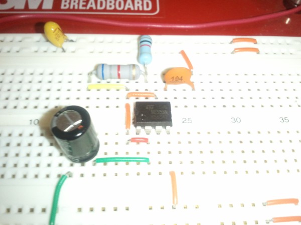
Pin 4 is connected directly to +5V. (Click for larger.)
* Connect a wire from the 5V power rail to Pin 8 of the 555 (the upper left pin).
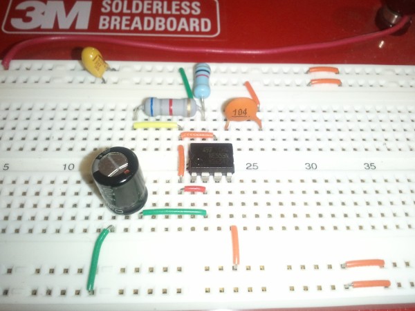
Pin 8 of the 555 is also connected directly to +5V. (Click for larger.)
* Connect a wire from the Ground power rail to Pin 1 of the 555 (the leftmost pin on the lower row.)
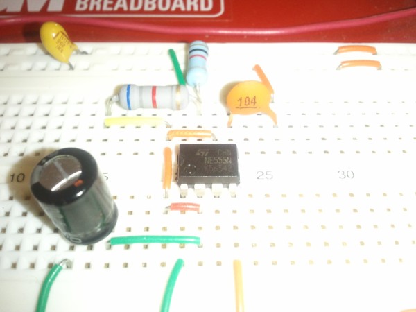
Pin 1 is connected directly to Ground. (Click for larger.)
* Connect a LED as shown. (The shorter pin should go to the Ground rail.)
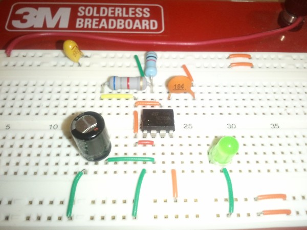
Place the LED near the 555, as shown, leaving room for the 470 ohm resistor. The shorter pin of the LED goes to Ground. (Click for larger.)
* Connect the 470 ohm resistor between Pin 3 of the 555 and the LED as shown.
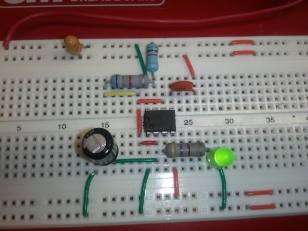
Connect a 470 ohm resistor between Pin 3 of the 555 and the positive (longer) lead of the LED, to complete the circuit. (Click for larger.)
The circuit should now be complete. Since it can be difficult to see everything that is going on through 2D pictures, here are some alternate-angle images of the timer resistors and 0.1uF cap, the 100uF cap, and the LED.


