Freestylin’

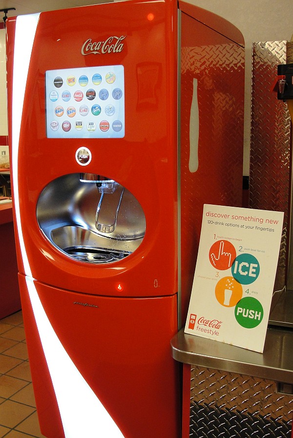
Just about the only thing better than a nice cold soda is a nice cold free soda. It’s even better when it’s a nice, cold, custom-selected, free soda from one of the new Coke Freestyle vending machines.

A Coke Freestyle machine. (Click for larger.)

But perhaps I should explain about the “free” part.

Since I worked an earlier-than-usual schedule today, I was able to make a Geek Pilgrimage to Moe’s Southwestern Grill in Suburban Station. I’m not usually one for authentic Tex-Mex (I’m sure it’s very good quality, but the spices would kill me). This particular Moe’s, though, had one of those new Coke Freestyle custom soda vending machines. I’d seen it through the store window while passing by after hours and had meant to try it. I researched it online and found that it custom-mixes each drink — not only from syrup, CO2 and water like normal soda fountains, but from an inkjet-printer-like assortment of dozens of flavors that it can mix in over a hundred combinations.

I stopped by Moe’s today and ordered a drink. When I got to the machine, though, most of the selections were grayed out — empty. This was unusual; I wouldn’t have been surprised if one or two were sold out, but it seemed that every good drink was out of stock.

This is the part where it pays to be a geek. I’d read about these machines online and found a video describing an Easter egg in the “Water” menu — a secret way to pull up the maintenance menu. I tried it, and it worked.

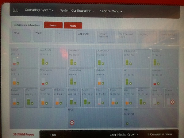
Surprisingly, the machine seemed to have enough syrup for Dr. Pepper, Coke, Barq’s, and several other good drinks. What it didn’t have, according to the supply screen, was “HFCS” (High Fructose Corn Syrup.) AHA. No sweet stuff == no way to make any of the good drinks!

The "secret" maintenance screen, showing a lack of HFCS. (Click for larger.)

The shift manager who was looking at the machine with me checked in the back, and said that it had a full box of HFCS. Apparently nobody had told the machine this, though. I poked around a bit more and found a resupply menu. A quick reset later, and the consumer menu was lit up correctly once again. The manager, grateful for the help, let me have my drink on the house. I’ve never enjoyed a Fanta Lime soda this much before. Maybe that’s because I’ve never had a Fanta Lime soda before.

It’s good to be a geek.


Posted in Current Events, Digital, Digital Citizenship, Reviews | 2 Comments

An Introduction to Programming: Lesson 00

Computer programming is increasingly becoming an essential skill in many professions. Computers are one of the most powerful and useful tools available to us, and the ability to use them to solve problems is an important one when working in any of the STEM (Science / Technology / Engineering / Math) disciplines.

More importantly, though, programming can be fun!

Here’s a quick introduction, presented as a series of lessons that will get you started writing programs for your own computer. I’ve chosen to use FreeBASIC as the programming environment for several reasons, including ease of use, versatility, and low cost (meaning, no cost). While languages like C are more widely used in industry, FreeBASIC lends itself quite well to a “C-like” style of programming. Transitioning to C or another similar language would be mostly a matter of learning different syntax.

To write and run a program, you’ll need to:

  • Download and install FreeBASIC;
  • Start up FreeBASIC
  • Write a simple program or two (which I’ll provide, for now); and
  • Click a button to compile and run the program.

Downloading and installing FreeBASIC:

  • Click here to download a copy of the FreeBASIC installer.
  • Once it’s downloaded, run it and click through the prompts. (The default choices are fine.)
  • That’s it! On to the next step…

Starting up FreeBASIC:

  • Double-click on the FBIDE icon on your desktop.
  • (I told you it was easy.)

Writing your first program:

  • The traditional first program is a “Hello, World” program — one that simply prints “Hello, World.”
  • Click on the “New” icon at the upper right corner of the FreeBASIC program window (or click on File, then New.)
  • Type in the following:
    print “Hello, World!”
    sleep 5000
  • Click File -> Save, and give your program a name.
  • Press F9 to compile your program (translate it into something your computer can understand) and run it.
  • A new window with the phrase “Hello, World” should appear for five seconds, then disappear.
  • Congratulations — you just wrote a computer program!

Getting it to do more

  • The “Hello, World” program is nice and all, but it’s not really a fitting task for a computer capable of billions of calculations per second.
  • Why not have the computer add up all of the numbers between one and one million? (Don’t worry — it won’t take long.)
  • Click File -> Close, then File -> New. (Working with computer programs is really just like working with documents in Word and similar programs.)
  • Enter the following text in the window. (We’ll cover what this means in later lessons.)
    dim as ulongint x, total
    total = 0
    print “Adding the numbers…”
    for x=1 to 1000000
    total = total + x
    next x
    print “The total is: “;total
    sleep 10000
  • Click File -> Save, give the program a name (maybe “number sum” or something), then press F9.
  • You should quickly get the answer: 500000500000.

The next lesson will cover how to get started writing your own BASIC programs.


Posted in Coding | Leave a comment

PIC startup debugging techniques

PIC microcontrollers are great little devices — reliable, fairly powerful, reasonably easy to use, generally available in DIP form factor, and very inexpensive. Sometimes, though, an overlooked configuration setting or a missed connection can cause a PIC-powered project to refuse to execute code.

Here is a generic version of the troubleshooting process that I usually go through (more or less in this order) if a PIC-based project doesn’t start up after having been programmed. Going through this checklist should cover most of the common problems that will keep a PIC from running. Double-check everything — even the “obvious” things like making sure power and ground are connected.


First, make a visual inspection of the circuit:

  • Is power connected to all Vcc pins?
  • Is Ground connected to all Vss pins?
  • Is this the correct type of PIC for your code?
  • Is the PIC seated correctly, especially if breadboarded?
  • Is the PIC in the correct orientation in the PCB or breadboard?
  • Are any of the PIC’s pins bent or otherwise not making contact?


Next, inspect the chip configuration in MPLab:

  • Is the correct type of PIC selected in MPLab?
  • Is the oscillator configuration set correctly?
  • Is the watchdog timer either disabled (or handled in code)?
  • Is the PWRON timer set? (This isn’t strictly necessary, but this helps ensure reliable startup)
  • Is the brownout reset configuration correctly set? (This may not be strictly necessary)


Check for correct programming procedure:

  • If connected to the programmer/debugger, is ~MCLR high?
  • Was the chip successfully programmed? (Check the output messages.)
  • Was it the correct program?


Next, look over the code for common mistakes:

  • Is the PIC actually executing code, but all TRIS registers are set to input?
  • Did you disable all unused peripherals which share the ports you’re using?
  • Did you enable all peripherals which you are using?
  • Are you using the correct definition file for this PIC?
  • Is your code going off into the weeds?
  • If your program reaches the end of the code, is this handled with a loop or a SLEEP instruction?
  • Is PCLATH set correctly when executing CALLs and GOTOs to other program pages?
  • Is PCLATH set correctly when returning from routines in other program pages?
  • Does your code execute a RETURN without a corresponding CALL?
  • Does your code execute too many (> 7) nested CALLs (including an infinite series of them)?


Next, inspect the signals and voltages at the chip pins:

  • Is the power at the correct voltage wrt Ground, on all power pins?
  • Is ~MCLR at Vcc (not floating, grounded, or at Vpp)?
  • Is the power clean? (try a decoupling cap or two near the PIC power inputs)
  • Using a ‘scope or at least a logic probe, check all inputs to the PIC (right where the pins enter the chip body). Are these signals what you would expect to see going into the chip?


Finally, try active debugging techniques:

  • Try another PIC (and remember to program it).
  • Try executing simpler code on the PIC.
  • Try disconnecting as many outputs as you can (shorted outputs could be causing a failure).
  • Try running a simple, known-good piece of code written for that same processor.


Posted in Assembly, Coding, Digital, Electronics, HOW-TO, PIC Microcontrollers | Tagged , , , | Leave a comment

Geek My Ride: Learning to speak OBD-II

Cars are pretty interesting, but generally not especially so from a Digital Electronics geek’s perspective. GPS navigation systems and fuel-consumption computers are cool, but for the most part, cars seem to be solidly the bailiwick of Mechanical types.

Relatively new cars, though, have a hidden secret. Every new car sold in the US since 1996 is required to implement OBD-II — a collection of protocols for the interchange of information about various automotive parameters. Information such as engine RPM, relative load (torque), vehicle speed, coolant temperature, and exhaust oxygen content can be monitored in real time. Engine trouble codes identifying problems that arise while the vehicle is being driven are also recorded — and when a problem is detected, the engine computer records the problem as well as a snapshot of the various system parameters at the time. This (in theory, at least) eliminates the all-too-familiar issue of car troubles which magically cure themselves while the vehicle is in for service. Even if a hard-to-diagnose problem is present, such as a loose electrical connection to an oxygen sensor, the EMC can note it while the car is going down the road, and store a snapshot of the conditions under which the error happened. It’s as if a mechanic’s assistant — or a Flight Engineer from the days of propliners — were always along for the ride.

All of this is good news to an automotive mechanic — but for a Digital geek, it can be described in one single word: DATA, and lots of it. Real-time engine performance data can be recorded and used for all kinds of things from learning to drive more efficiently (using real-time fuel efficiency calculations) to detecting possible problems before they cause trouble (for instance, detecting transmission slippage or changes in fuel consumption or oil pressure). All that is needed is some kind of interface to the OBD-II system, and some software to collect and interpret the data.

SparkFun, as usual, has come up with a nearly-turnkey solution to most of this. Their OBD-II interface board, along with the associated cable, allows semiautomated querying of the various bus protocols supported by OBD-II. Requests are translated into CAN, PWM, VPW, DCL, and various other protocols (OBD-II has more official “languages” than Switzerland.) The computer side of the interface board is much easier to work with: standard 5-volt serial TTL signaling. SparkFun even helpfully provides an FTDI cable which can translate this TTL interface into a virtual COM port on a PC.

SparkFun's OBD-II interface board.

The OBD-II connector is always located in the passenger compartment, within three feet of the driver. Here is a database showing the approximate location for many makes and models. For my Escort and my wife’s Sable, the connector was found below the driver’s side dashboard, to the left of the steering wheel column.

Once the board is connected to the OBD-II connector and to the computer, a few commands are all that is needed to start reading data. Sending a query code of 010C returns the engine speed (in quarter-RPM, encoded in hex). Sending a query of 010D returns the current vehicle speed in km/hr (also encoded in hex).

Once you’re connected, the next step is learning the language. SparkFun provides a good bit of documentation and some examples on their site, and Wikipedia also has a nice list of many of the basic PIDs and what information they return.

With a bit of programming, this information can be recorded, logged, and presented in nearly any format imaginable. Here, for example, is a plot of engine RPM vs. vehicle speed, for part of a recent trip I took.

A scatterplot of RPM vs. vehicle speed, for part of a trip. (Click for larger.)

The availability of the OBD-II bus not only allows the collection of data using a PC, but also provides a way to implement a custom vehicle computer system using an Arduino or similar microcontroller. (More about this, later!)


Posted in Arduino, Automotive, C, Coding, Digital, Electronics, HOW-TO | Tagged , , , , | Leave a comment