A Confusion of COM Ports

I like serial-port communications, but this is ridiculous.

Whenever a new USB serial device is connected to a Windows computer (and/or apparently whenever an existing USB serial device is moved to a new USB port), Windows assigns it a new COM port number. Back in the good old days, there was generally COM1 and COM2 — typically for a mouse and modem — and the addresses were set in hardware with jumpers or DIP switches.

Fast-forward to today’s environment, including Arduinos, Bluetooth serial devices, USB-to-serial cables, and others. I’m up to COM29 with no end in sight. Most of these are the ghosts of various devices plugged in to various USB ports. The drivers are all still installed, and they’ll be redetected when plugged back in.

Deleting unused COM ports in Windows isn’t as straightforward as perhaps it should be, since Device Manager doesn’t list non-present COM ports by default. Fortunately, an article on Microsoft’s Knowledge Base shows how to change this. Here’s how:

  • Open a command prompt
  • Type      set devmgr_show_nonpresent_devices=1    <enter>
  • Type      start devmgmt.msc  <enter> to start Device Manager
  • Click     View –> Show Hidden Devices.
  • The COM ports are listed under “Ports (COM & LPT).” Have at ’em!

Incidentally, this solved the mysterious   “avrdude: stk500_getsync(): not in sync: resp=0x86” error message I was getting when uploading an Arduino sketch. Apparently even the Arduino IDE had had enough.

 

Posted in Arduino, HOW-TO, System Administration | Leave a comment

Electoral College Reckoner

The US Presidential election system is not the most straightforward thing in the world. The President is not directly elected by popular vote, but is instead elected by the members of the Electoral College. These members are chosen by the individual states, with each state receiving as many electors as it has members of Congress. Most states select their electors on a winner-takes-all basis. Maine and Nebraska use a split system whereby some electors are determined by popular vote and others are determined by the popular vote winner in specific electoral districts.

Since there are five hundred thirty eight members in the Electoral College and a clear majority is needed, two hundred seventy electoral votes are needed for a victory. This has various effects on the Presidential campaigns — mostly involving candidates spending a lot of time and money courting votes in large “swing states” (states with a large number of electors where the outcome is uncertain.)

Various pollsters and pundits have tried to predict the outcome of the election. Nate Silver’s “Five thirty eight” blog has come up with an estimate of the odds of each candidate winning each state’s electoral votes (including Congressional districts in Maine and Nebraska.) From this, it’s possible to predict the outcome of the election, using Monte Carlo analysis.

Using Five Thirty Eight’s data (text file contains district abbreviation, odds of a Democratic victory in that district, and its number of electors for this year), I ran the simulated 2012 Presidential election (FreeBASIC code) one billion times. (Hey, if it’s worth doing, it’s worth overdoing!)

The results are encouraging for a secular, liberal/libertarian geek like me:

Runs: 1,000,000,000
Democratic victories: 960,093,075
Electoral College ties: 2,608,646
Republican victories: 37,298,279

Democratic victory %: 96.01%
Electoral College tie %: 0.26%
Republican victory %: 3.73%

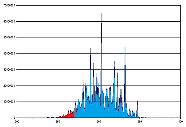
Here’s a histogram of the relative probability of each number of electoral college votes for President Obama. (Anything 270 or greater is a Democratic victory.)

A histogram of the projected probabilities of the Electoral College outcomes, according to the simulation. (Click for larger.)

I hope Mr. Silver’s analysis is correct. We really don’t need another four years of corporate cronyism and Bible-thumping anti-intellectualism.

Posted in BASIC, Coding, Current Events, Digital Citizenship, Math, Science | Leave a comment

PIC I2C Library

Having spent the better part of the day writing I2C routines for the PIC16F887 from scratch (because the supplied Hi-Tech libraries didn’t seem to work), I figured I might as well package them up into a library for future use, available here.  (These were written for a PIC16F887 using Hi-Tech C, but they should be fairly easy to port to any other platform with a standard C compiler.)

Usage is fairly straightforward:

I2C_ReadRegister(char deviceAddress, char registerAddress);

I2C_WriteRegister(char deviceAddress, char registerAddress, char Data);

The routines are simple and straightforward: single-master-only and single-byte-transaction-only. I may get ambitious enough to update them later on…

I consider these routines to be either late alpha or early beta at this point (meaning that they seem quite reliable so far, and most of the major bugs appear to have been squashed.) Specifically, they have been tested with Sparkfun’s MMA8452Q Triple-Axis Accelerometer. If you notice any bugs or have suggestions for improvements, I’d appreciate a heads-up.

“Share and enjoy!”*

Posted in C, Coding, Digital, PIC Microcontrollers, Resources | Tagged , , , , | Leave a comment

Euclidean Construction

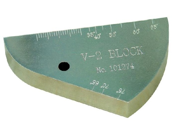
The other day, I had an unusual request at work. (Actually, unusual requests aren’t really that unusual around here, which is one reason why my job is generally pretty cool.) Part holders were needed for ultrasonic calibration blocks — and these blocks had a strange, nonlinear shape.

The calibration block in question. (Click for larger.)

Using calipers, I determined that the block was about 25.4mm (one inch) thick — and therefore, was probably calibrated in inches. The length of the top (hypotenuse?) measured right about three inches across, so this seemed to confirm the idea.

How to measure the diameter of the semicircles, though, since only a small arc of each was available? High-school geometry, and a few assumptions, provided the answer. Both arcs looked to intersect the top at a 90-degree angle, meaning that the center of each arc had to be somewhere along that line. For the larger arc, a chord can be constructed between the two endpoints. Taking the perpendicular bisector of this arc (with a compass and straightedge) provides a bisector of the arc. The intersection of this line with the top of the piece locates the center of the circle. It turned out to have a radius of two inches, and its center turned out to also be the center of the smaller arc (with a radius of one inch).

The final question was where to begin and end the arcs. Measuring the distance across the larger arc resulted in a length of very nearly two inches. Since this made sense (calibration blocks normally use nice round number measurements like this), I decided to treat this as exact. Using a virtual compass, I drew a third circle with radius two inches to locate the end point of the larger arc. Finally, I reasoned that the line segment from this point was tangent to the smaller circle, and added it accordingly.

The construction for the calibration block shape in Google SketchUp. (Click for larger.)

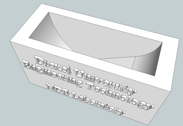
Now that the measurements were known, it was fairly straightforward to design a holder jig in Google Sketchup and send it to our 3D printer. Score one for high-school geometry!

A Google SketchUp rendering of the holder. (Click for larger.)

Posted in Design, Drexel, Math, Reverse Engineering | Leave a comment