BMP file format

Since uncompressed bitmaps are a one-to-one representation of pixels in an image, they are one of the simplest formats to generate, if you are writing your own code. Here is a description (plus FreeBASIC code, which works well enough as pseudocode) of how to output a .bmp file, given an array of pixels.

In order to make the process as straightforward as possible, I will make several (hopefully reasonable) assumptions:

  • The image exists in memory, in a format (an array, for instance) which can be easily read in random-access order;
  • A color depth of 24 bits is used (eight bits each for Red, Green, and Blue);
  • BITMAPCOREHEADER (the simplest header) is used; and
  • The height and width of the image are reasonable and known.
    (I will call these variables XSIZE and YSIZE.)

Values given here are in hexadecimal. All multi-byte values in BMP files are little-endian.

Bitmap files consist of three parts:

  • The bitmap header;
  • The DIB header; and
  • The pixel data array.

The bitmap header is straightforward enough:

  • Two bytes to denote a bitmap file: ASCII “BM”, or hex 0x42 0x4D
  • Four bytes, representing the size of the BMP file in bytes.
  • Two bytes reserved: these can safely be 0x00 0x00.
  • Two more bytes reserved: these can also be 0x00 0x00.
  • Four bytes for the offset address of the pixel data.
    (If using BITMAPCOREHEADER, this is 0x1A 0x00.)

The BITMAPCOREHEADER is next, and also relatively simple:

  • Four bytes for the size of the header (14 bytes, so 0x0E 0x00 0x00 0x00).
  • Two bytes for the image width in pixels;
  • Two bytes for the image height in pixels;
  • Two bytes for the number of pixel planes (must be 0x01 0x00); and
  • Two bytes for the bits per pixel (0x18 0x00 in our 24-bit example.)

The last structure is the bitmap data itself. This is three bytes per pixel, with each row padded to the next multiple of four bytes, as needed. Each pixel is in BBGGRR order.

We now have all of the pieces of information we need to create the bitmap file…

  • Output ASCII “BM” (0x42 0x4D)to the file
  • Calculate the size of the file:
  • – 14 bytes for the bitmap header, plus
  • – 12 bytes for the DIB header, plus
  • – The number of rows (image height) times the row size in bytes.
    (The row size is the image width, times three, rounded up to
    the next multiple of four, if needed.)
  • Write this figure to the file, in little-endian hex, using four bytes.
  • Write 0x00 0x00 0x00 0x00 to the file, for the two reserved fields.
  • Write 0x1A 0x00 (representing the 26-byte offset for the start of data.)
  • Write 0x0C 0x00 0x00 0x00 (representing the DIB header size.)
  • Write XSIZE in two-byte little-endian hex.
  • Write YSIZE in two-byte little-endian hex.
  • Write 0x01 0x00 for the number of pixel planes;
  • Write 0x18 0x00 to represent 24 bits per pixel.
  • Loop over the number of rows (YSIZE) in the image:
  • – For each pixel in that row, write its image value in little-endian hex (BBGGRR)
  • – At the end of the row, pad it with zero to three extra bytes to make the number of bytes in the row a multiple of four.
  • Close the file. You’re done!

Here is an example in FreeBASIC, which produces a simple 3×3 bitmap.


Posted in BASIC, Coding, HOW-TO | Leave a comment

Novus 4525

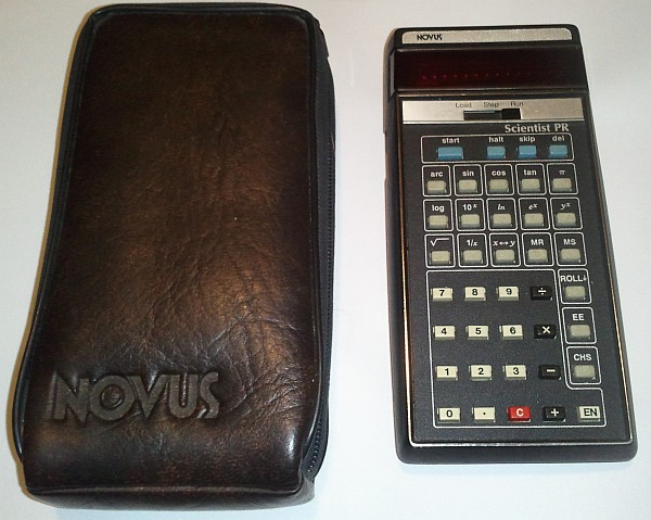
You never know what you’ll find in thrift stores. The other day, I found an interesting old calculator at a local Goodwill. The LED display and single-function keys hinted that it was of 1970s or 1980s vintage — but an unusual “load/step/run” switch implied that it was in fact a programmable calculator or simple computer. Sequences of operations up to 100 steps long can be loaded in and then run. It’s not really a proper computer — more of a calculator with macro capability.

The Novus 4525 and case. Not shown: the $0.97 Goodwill price tag. (Click for larger.)

True computer or not, this was apparently one hell of a calculator, back in 1975. According to the April 1975 issue of IEEE Spectrum, the Novus 4525 retailed for $169.95. That’s about $723 in 2012 dollars.

The first step in getting it running again, since it didn’t come with its AC adapter, was to determine what kind of power supply it needed. Looking inside the case, the barrel connector appears to be directly connected across a three-cell NiCd battery — with the tip connected to the positive terminal. The battery is a Radio Shack replacement pack number 23-170 (three 900mAh NiCd AA cells in series.) Since this doesn’t seem to be the original battery pack, it’s hard to say what that was — perhaps a sealed lead-acid pack? At any rate, a roughly 4VDC power supply should do the trick. For now, I just charged up the NiCd pack with a bench power supply.

One of the distinguishing features of the Novus is its use of Reverse Polish notation (RPN), also known as “postfix notation.” In order to, for example, add four and five, the user enters 4, ENTER, 5, +. Postfix notation is associated with a stack, and therefore the Novus implements a four-position stack. Mathematical expressions can be entered unambiguously (no need for rules such as PEMDAS), as long as the user is careful not to overflow the stack.

For someone used to modern calculators, the Novus’ accuracy can be somewhat disquieting in certain situations. Performing a straightforward operation like 3*3 gives the expected result of 9. A slightly more complex method such as 3^2, however, gives an answer of 8.9999988 — and takes just over two seconds to come up with this dubious answer.

According to the manual, the Novus’ programming capabilities seem relatively limited. Operations that could normally be entered manually can be executed semi-automatically — but the calculator seems to lack any looping or branch control functionality, making it not Turing-complete. That functionality would have to wait a few more years, for calculators like the Tandy Pocket Computers. Still, it’s pretty impressive for a pocket calculator from 1975.


Posted in Digital, Nostalgia, Reviews, Toys | 1 Comment

BASIC Stamp board review

While browsing through a local Radio Shack the other day, I noticed some BASIC Stamp boards in stock. Since new dev boards are always interesting — and since I’ve been programming in BASIC since the days of the dinosaurs early ’80s, I decided it was time I tried one. I certainly like microcontrollers, and for better or worse, BASIC is still my “native” programming language. A BASIC Stamp board is therefore a no-brainer, right?

Well, yes and no…

Setup:

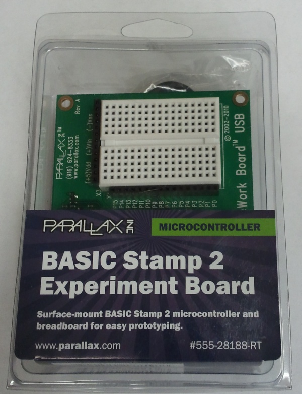
Physical setup of the board is pretty straightforward. To save on cost and packaging, no software is included; you download it from Parallax’s site. Bonus points for environmental responsibility: check.

The BASIC Stamp 2 "Home Work Board USB" in its package. (Click for larger.)

Unfortunately, Parallax’s site doesn’t have a very intuitive process for locating the board drivers. The directions on the package steer you to www.parallax.com/rt (which I won’t link to and add to the confusion), but that page just offers vaguely-helpful instructions on how to find your product number and type it in. Doing so lets you locate the product page for the specific board you have. Hunting around on that page turns up a link to Parallax’s common software download page for most or all of their BASIC stamp boards (begging the question, why did I have to enter in the product number??)

Once you locate the BASIC Stamp software download page, things fortunately get a lot easier. The page has an easy, obvious “1-2-3” chart front and center. Nice! Click on the first link, install the software, and connect up the board. Simple.

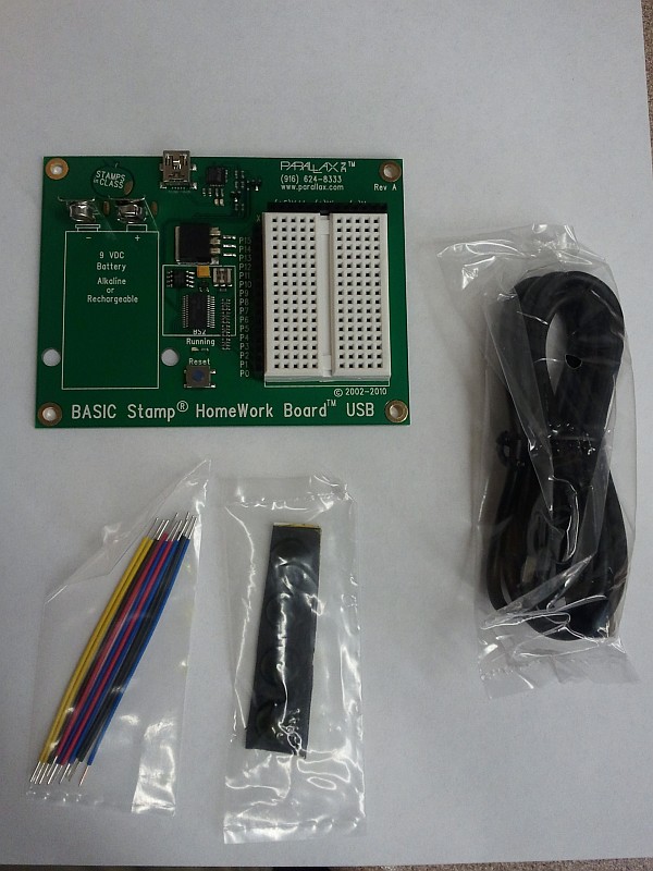
The box contains the board, a cable, jumper wires, and non-skid feet. (Click for larger.)

Download the software? Check.

Run the installer? Check.

Plug in the device? Check. (The USB drivers loaded nicely on  Windows 7/64bit.)

Launch the software? Check.

Run examples? Uh oh. Unlike the easy “Examples” menu in the Arduino IDE, Parallax’s Basic Stamp Editor software starts up with its default directory in C:\Windows. This is not only useless (that’s not where the examples are or where your programs ought to go) — but potentially dangerous if people start digging around in the Windows directory structure. These boards are marketed to primary and secondary-school students, and this is asking for trouble.

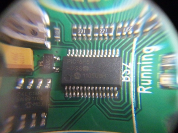
Guessing that the correct location was in the “Program Files (x86)\Parallax” directory (it was), I soon was in more or less the right place. The next challenge was to determine which version of BASIC stamp the board had. This, again, wasn’t specified. A quick check of the packaging turned up a reference to a “BASIC Stamp 2 chip,” so I went with that. (The actual chip turns out to be a garden-variety PIC, presumably with special firmware.)


The star of the show turns out to be a Microchip PIC16F57. (Click for larger.)

I fired up a random example from the “BS2” folder — a “connection test” program. It ran, but reported no boards found (even though the board’s lights blinked when programming it.) I tried a few more examples with the same result — no board found.

At that point, I decided to try applying 9V to the battery terminals, theorizing that the board didn’t get its power from USB (like the Arduino boards do.) This worked, and the board was soon running the connection-test example correctly.

Programming

I loaded up another example — “HIGH_LOW.BS2” — and ran it. A LED that I had connected between P0 and Ground blinked dutifully at 1Hz. Success. I modified the delay times to 100ms instead of the default 500ms, and the LED was soon blinking at 5Hz. So far, so good.

Performance

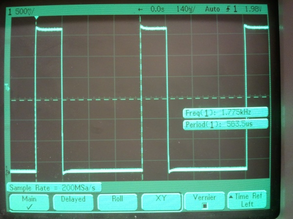
I decided to see what the board could do with the throttle wide open. I commented out the “pause” lines (the board’s dialect of BASIC uses the usual apostrophe-for-comment convention), and re-ran the program. The LED came on dimly (as expected), and the oscilloscope showed a high-frequency output. Dialing in the ‘scope readout showed an output at roughly 1.775kHz, with a 25% duty cycle.

The output from a simple "high, then low, then repeat" program. (Click for larger.)

Writing this code in native PIC assembly would produce the same 25% duty cycle: One instruction would be needed to raise the output; one more would lower it, and a “GOTO” instruction to loop back to the beginning would take two cycles (due to the way the PIC uses a simple two-stage pipeline to execute code.)

A PIC clocked at 8MHz would execute code at two million instructions per second (2 MIPS), counting GOTOs and such as two instructions. If this high/low/repeat code were written in assembly, it would take four instruction cycles to execute, resulting in one cycle every two microseconds, or a frequency of 500kHz. The observed frequency, by comparison, is some two hundred eighty times slower than this theoretical maximum. (…and most PICs, including the 16F57, can run much faster than 8MHz if need be.)

That’s not merely slow — that’s glacial! Even the Arduino executes naive C++ code faster than that. Unless the PIC is being clocked extraordinarily slowly, either it’s running the BASIC code as an interpreter (a bad idea), or the compiler is very inefficient.

This calls for more investigation, but my guess is that performance is not high on the priority list for the BASIC Stamp.


Posted in BASIC, Coding, Digital, Electronics, PIC Microcontrollers, Reviews, Toys | Leave a comment

Drill Bits Of Unusual Smallness

One of the fun things about technology is that there are so many diverse subfields that nobody can stay current with all of them. Occasionally, you come across a tool or process commonly used in another field that seems amazing to those not used to it.

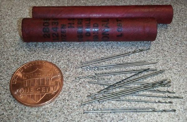
One of the students where I work recently brought in a set of micro-sized drill bits. These are a fraction of a millimeter in diameter; the smallest chuck for my Dremel tool wouldn’t hold them. Even the drill bits for the LPKF PC board milling machine that we use are larger.

I don’t know what they’re generally used for (pilot holes for micro-sized screws?), but whatever it is, it involves extraordinary precision!

The set of micro-size drill bits. (Click for larger.)

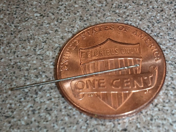
A detail view of one of the smaller bits. (Click for larger.)

Thanks for sharing, Mike!


Posted in Metalworking, Tools | 1 Comment