I Have Seen Nirvana, And It Is In Shenzhen…

On the one hand, I would love to take about $1000 cash and just go shopping here.

On the other hand, if I brought my wallet, I’d be broke for the next six months for sure. Maybe it’s a good thing that I’m some ten thousand miles and a travel visa away?

Posted in Analog, Components, Digital, Electronics, Resources, Tools, Toys | Leave a comment

Superposition

One useful tool when performing circuit analysis is superposition. By considering voltage and current sources one at a time (setting all others equal to zero volts or zero current), voltages and currents in an electrical network containing any number of sources can be analyzed.

In a simple circuit, DC analysis is straightforward. Resistances in series, parallel, or simple combinations of the two can be numerically lumped together, and the resulting currents and voltages calculated using Ohm’s Law. In the circuit below, for example, the two central 1k resistors can be viewed as a single 2k resistance. This, in parallel with R2, forms 1k of resistance. When R1 is added, the total circuit resistance is 2k. By Ohm’s Law, 5mA of current flow through the circuit. It is fairly straightforward to see that all 5mA flow through R1, and that 2.5mA flow through R2, R3, and R4.
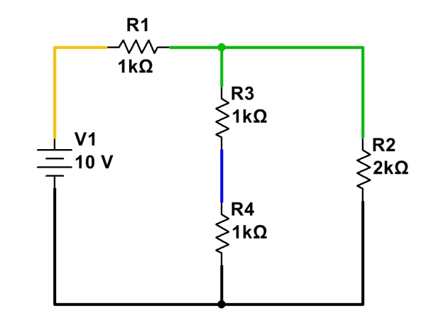
A simple, easy-to-analyze DC circuit.

When more than one voltage and/or current source is involved, though, things get trickier. Resistances cannot be simply combined as before, since there could be voltages and/or currents due to several different sources. Another approach is needed.
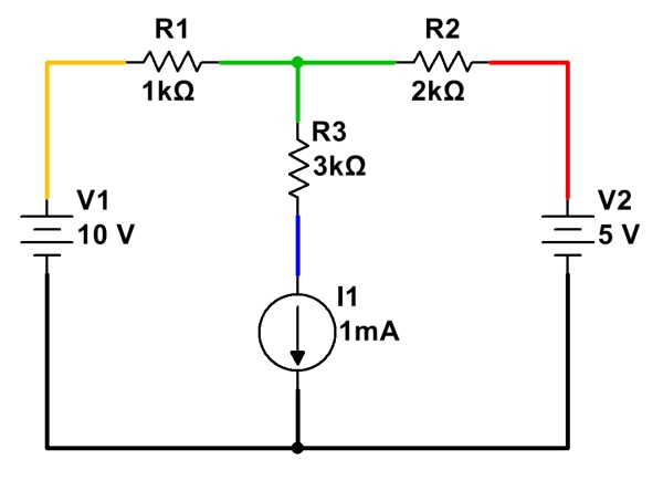
A more complex circuit, with multiple independent sources. (Click for larger.)

Fortunately, superposition provides a straightforward, practical way to analyze circuits with multiple power sources. By following a few simple steps, voltages and currents can be calculated through a circuit of arbitrary complexity. (For some configurations, simplification using Wye-Delta conversions may also be needed.)

To analyze current flow in a circuit with multiple sources, analyze the circuit with only one source at a time present, setting all other sources temporarily to zero:

  • Replace all voltage sources not being analyzed with a short (zero voltage), and
  • Replace all current sources not being analyzed with an open (zero current).

Once these substitutions have been made, re-analyze the circuit, noting the current flow in each branch due to this source. Do the same for any remaining sources, re-enabling them in the circuit, and setting the already-analyzed source to zero voltage or zero current, as appropriate.

Here is a simple example of circuit analysis of using the above example, with two voltage sources and a current source:
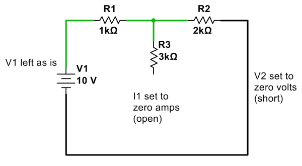
First, calculate and note all currents due to V1 with other sources V2 and I1 removed. (Click for larger.)
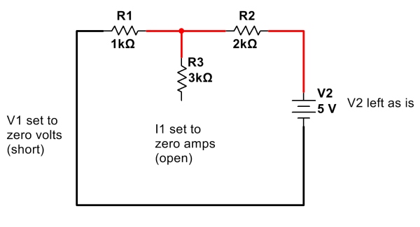
 

Next, calculate and note all currents due to V2 only, with V1 and I1 removed. (Click for larger.)
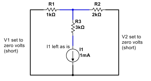
 

Finally, calculate and note all currents due to I1, with V1 and V2 removed. (Click for larger.)

After calculating and noting current flows due to all of the sources, add them up. One way to do this is to assign a color for each source, and note the current flow due to that source through each resistor. (Remember to note which direction each current component flows; current flows going in the same direction add, but currents flowing in opposite directions cancel!)
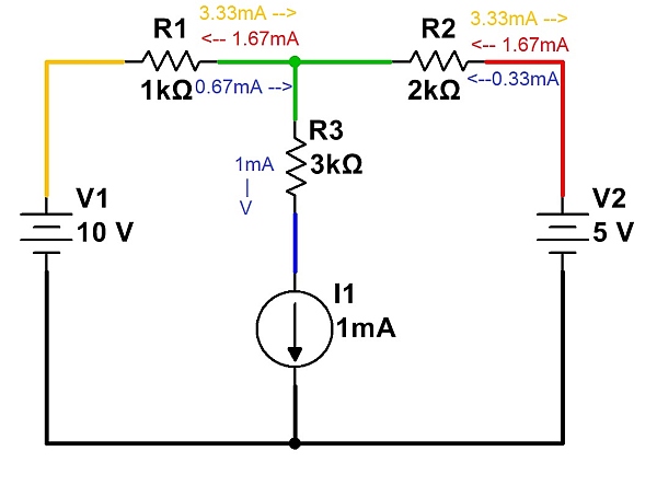
Currents from each source are noted independently. These are then added to determine total current. (Click for larger.)

Once all of the currents have been noted, they can be added (and subtracted, depending on direction) to show the total current flow…
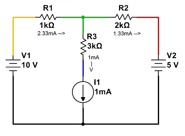
The total currents in each branch, summed. (Click for larger.)

Note that Kirchoff’s Current Law (net current flow into or out of a point is zero) must be satisfied for each point in the circuit. For example, at the node represented in green, 2.33mA of current is flowing in through R1. This current must leave the node, and therefore 1mA flows through R3 and 1.33mA flows through R2. The net current into the node is therefore zero, so no charge accumulates over time.

Posted in Analog, EET201, Electronics, Fundamentals | Leave a comment

How To Use A Digital Multimeter (DMM)

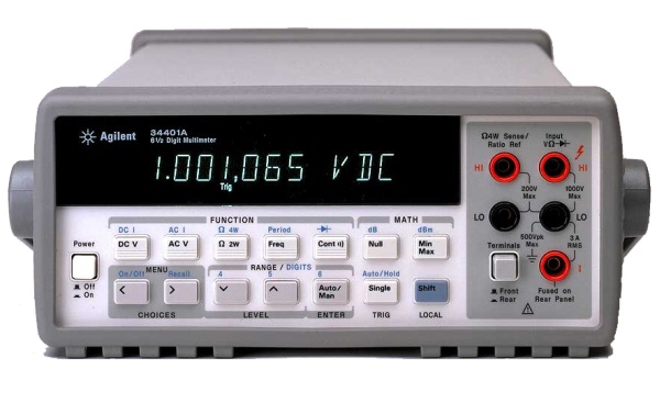
Digital Multimeters (DMMs) are quite versatile devices. Typically, they can be used to measure voltage, current, and resistance. Many DMMs are also capable of other measurements, such as continuity (an extension of the resistance function, actually) and frequency. Some are also capable of basic math operations on the measurements performed, including null offset and maximum/minimum readings. Here is a brief guide to using a DMM — specifically, an HP/Agilent 34401A. This type of meter is a “bench” meter — meaning that it is intended for use on an electronics workbench. It is somewhat portable, and includes a handle, but is significantly bulkier (and a bit more fragile) than handheld meters, so it is usually found on a workbench or in a lab. On the plus side, it is far more accurate than most handheld meters.

The Agilent 34401 Digital Multimeter (DMM). (Click for larger.)


Measurement of voltage

The most basic function of a DMM is as a basic voltmeter. Most DMMs are autoranging, meaning that they automatically select the correct voltage range (millivolts, volts, etc) based on the measurement being made at the time. To measure DC voltage with the 34401A:

  • Turn on the meter using the power switch on the left end of the front panel.
  • Press the “DC V” button (if you will be measuring DC voltages.)
  • Connect the negative probe (typically black in color) to the rightmost black “LO” port. (The two ports in the left column are used for four-wire resistance measurements, which are not covered in this guide.)
  • Connect the positive probe (typically red) to the upper right “HI” port.
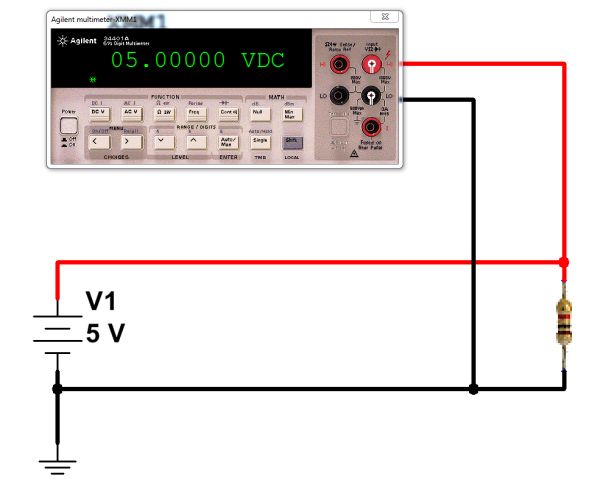
  • Connect the probes to the circuit under test. Voltage is measured in parallel with a component, so you would not break the circuit to measure voltage.
  • Read the voltage data on the meter.

Connect the voltmeter in parallel with the resistor to measure volts. (Click for larger.)


Measurement of current

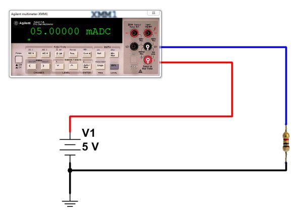
Another useful function of a DMM is as an ammeter — a meter designed to measure current flow. Since current flow is measured within a conductor, the meter must be actually inserted in the circuit in order to measure this flow. (There are “clamp” ammeters which do not work this way, but they are not covered here.) Because of this requirement, measuring current in a circuit is done differently than measuring voltage — the connections are made differently. Instead of simply clipping on to a circuit, the DMM replaces one of the wires in the circuit, and the current is made to flow through the meter. It is important to make sure that the meter replaces a wire of the circuit in this way, or else it could cause a short circuit. (That is, you need to break a connection, then insert the DMM in the gap.)
To measure DC current with the 34401A:

  • Turn on the meter
  • Press the blue SHIFT button once, then press the DC V button. This will put the meter into “DC I” (DC current) mode.
  • Connect the negative lead to the right “LO” port
  • Connect the positive lead to the right “I” port (at the lower right).
  • Disconnect power to the circuit to be tested
  • Choose a wire in your circuit where you will measure current. Disconnect it.
  • Connect the black lead to one end of where the wire was (ideally, its more negative end.)
  • Connect the red lead to the other end of where the wire was (ideally, its more positive end.)
  • Reconnect power to the circuit to be tested.
  • Read the current value on the meter’s display. (Note mA or A, as well.)

Connect the DMM in series with the resistor to measure current. (Click for larger.)


Measurement of resistance

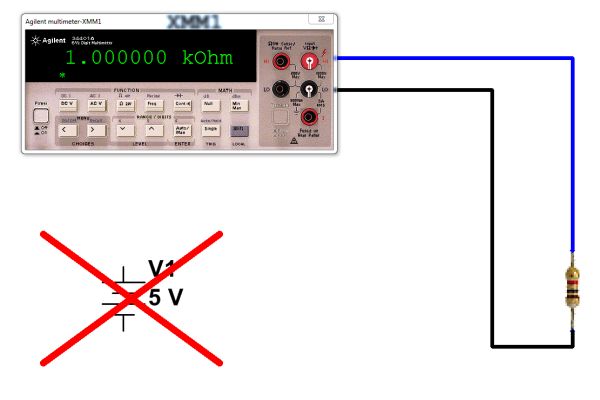
DMMs can also function as ohmmeters, allowing the measurement of resistance. Unlike measurements of voltage and current, this must be done with power disconnected from the circuit. (In fact, since parallel resistances can affect the measurement, resistance is usually measured with the component disconnected from the circuit, at least at one end.) When measuring resistance, the meter passes a small amount of current through the resistor and measures the resulting voltage. To measure resistance with the 34401A:

  • Turn on the meter
  • Press the “Ω 2W” button.
  • Connect the negative lead to the right “LO” port
  • Connect the positive probe (typically red) to the upper right “HI” port.
  • Disconnect at least one end of the resistor to be tested from the circuit.
  • Connect one probe to one lead of the resistor to be tested.
  • Connect the other probe to the resistor’s other lead. (Direction doesn’t matter.)
  • Read the resistance value on the meter’s display. (Note mΩ, Ω, kΩ, or MΩ.)

To measure resistance, disconnect the power supply and connect the DMM across the resistor to be measured. (Click for larger.)


The 34401A has many other measurement capabilities (frequency, continuity, four-wire resistance, diode check, etc.) It can even connect to a computer via RS232 or GPIB for automated measurements.


Posted in Analog, Drexel, EET201, Electronics, Fundamentals, HOW-TO, Tools | Leave a comment

Short And Sweet

As any Linux aficionado can attest, “less is more.” While this is not always true of everything, it certainly applies to URLs. “www.paleotechnologist.net” is a cool domain name, but it doesn’t readily lend itself to terse media such as QR codes.

I therefore present a new, shorter site alias:   pt0.us (with a zero, not an “o.”)

Scan me!

URLs at pt0.us point to the same content as paleotechnologist.net (and paleoengineer.net and paleoengineer.org, for that matter). New and existing content will be available at all of these domains.

Why PT0? Simple:

  • PT stands for PaleoTechnologist;
  • Zero is the most central, the most unique, and possibly the most important of the integers;
  • …and while .us is geographically appropriate as a TLD, I chose it for its shortness.

Rumors that this is in preparation for site-related QR code generation are completely unsubstantiated. That’s not to say that they are incorrect, however!

Posted in Internet | Tagged , , | Leave a comment