How Not To Code

Recently, my friend Dan shared a thought-provoking picture of a quote by Martin Golding:


"Always code as if the guy who ends up maintaining your code will be a violent psychopath who knows where you live." --Martin Golding

Words to live by.

When I first started writing programs back in the Dark Ages (1980s), I wasn’t even aware that coding styles existed. Not only did I probably break every applicable rule in the Embedded C Coding Standard — my code was usually cryptic, terse, and would have been very very difficult to scale.

Nowadays, looking through my code library, I can almost tell when I wrote a piece of code, based on how it looks. Here’s an example of some of my oldest BASIC code that I could find: (The file, helpfully, was called “T.BAS”)

5 PRINT TIME$
10 FOR X = 1 TO 1000000
20 P = 1 / X
30 NEXT X
40 PRINT TIME$

This is Dark Ages code for sure. No comments or other documentation whatsoever, single-letter variable names (the only reason TIME$ is there is that it’s built-in), and LINE NUMBERS. Fortunately, this program is very simple, so it’s an easy enough task to figure out what it does. (It’s a very simple benchmark for a division loop.)

Here’s how I might write it these days:

‘Division loop benchmark test program (FreeBASIC)
‘Notes time to execute one million divisions of size double
‘M. Eric Carr / eric(at)(email address)

‘Variable declarations
‘———————-
dim as double quotient
dim as ulongint curNum

‘Note the start time
print “Doing 1,000,000 divisions…”
print “Started at: “;time$

‘Run a loop of 1,000,000 divisions
for curNum = 1 to 1000000
quotient = 1/x
next curNum

‘Note the end time
print “Ended at: “;time$

end

This is a little better. It’s still flat code (no subroutines or other hierarchical structure), but it’s simple enough that such structure isn’t really needed. The documentation and intuitive variable names make it much easier to maintain, the output now tells the poor clueless user what is going on, and the global variables are at least declared.

Here are some other helpful tips to make your code more maintainable:

  • Use comments liberally. If it isn’t immediately obvious what a line of code does, document it inline with comments. In fact, it can be helpful to write the entire program in pseudocode, as comments, and then go back and fill in the mechanics.
  • Use intuitive, descriptive variable names. A variable named “x” can mean many things, but one named “currentOutdoorTemp” is a bit more descriptive. When using a compiler, this has zero runtime cost — the compiler will translate the variable names into memory locations automagically, anyway.
  • Use structured programming. If you have several pieces of information that belong together, consider using custom data types. If you have a program that is more than a dozen lines of code or so, it has probably become large enough to be split into subroutines. Doing so modularizes the task of programming, making the program easier to understand and far easier to maintain, modify, and scale.
  • Along with the “structured programming” theme, use as few global variables as possible. They can be modified by not only the main code, but by subroutines, making it potentially very difficult to diagnose what is happening. For multithreaded applications, this becomes crucial; any global or shared variables will require good, solid mutexes.
  • Don’t use GOTO statements unless absolutely necessary. These can often be avoided even when programming in assembly. (My own goal is to never use GOTOs, with the exception of a single GOTO at the end of the main loop, when coding in assembly.) GOTO statements can make code execution very difficult to trace.

…because all too often, the violent psychopath who will have to maintain your code — is YOU!

Posted in BASIC, Coding | Leave a comment

Resistive Security Loops

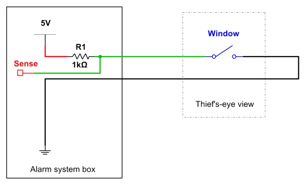
Perhaps the most basic form of electronic security system involves a buzzer or bell set to go off if a loop of wire is cut. Sensors, such as door position switches and sliding window contacts, can be inserted into this loop, breaking the circuit if a window or door is opened. When the loop is cut (say, by a window switch opening), an alarm bell can be made to ring.

Naive_sm

A simple, naive security system. (Click for larger.)

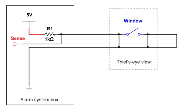
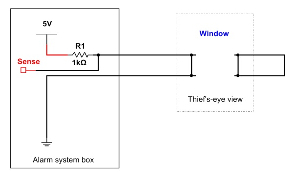
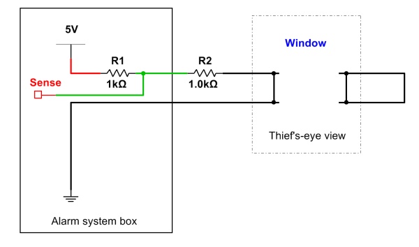
This simple approach, though effective, has a weakness. If a nefarious individual wished to circumvent this protection, he or she need only expose a section of cable, short it in two places (who knows which side of the wire goes to the alarm), and then cut it between the two shorts. Whether the security system was on the right or left side of the cut, the loop would still be complete, and current would still flow. Make these shorts on either side of a door or window sensor, and you can then open the door or window without triggering the alarm. In addition, all of the sensors “downstream” of the cut are now taken out of action.

Naive_defeated_step1_sm

First, the thief shorts the wire on both sides of the switch (he doesn’t know which end goes to the alarm system)…

Naive_defeated_step2_sm

…then, the wires are cut, and the window is opened. (Click for larger.)

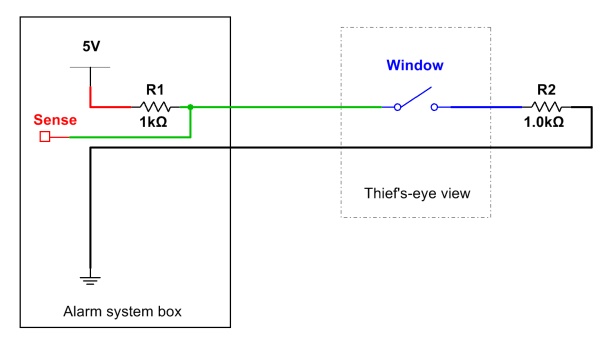
What can be done to detect such dastardly meddling? Plenty. Rather than making a simple current loop, an end-of-loop resistor can be incorporated, and the system set to monitor the loop for a specific expected resistance. Any would-be burglar would then have to not just short the cable, but provide the appropriate resistance. Without prior knowledge of the system, this would be essentially impossible; it would be quite tricky even if given a schematic, wiring layout diagrams, and a good portable electronics lab. Even if the correct resistance (and direction to the control box) were known, inserting a fake end-of-loop resistor while maintaining a constant line resistance would be very difficult.

Far_rx_sm

This one is harder to defeat. (Click for larger.)

far_rx_tampered_sm

Here, a thief has tried to defeat the added-resistor system, but the electronics sense a dead short and trigger a tamper alarm. ARF ARF — GOTCHA! (Click for larger.)

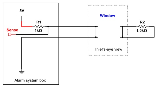
However, a security system is only as good as its weakest link –including the installer. Loop resistors do not, by themselves, somehow imbue the wire with magical properties which make it immune to tampering. If placed at the near end of the loop (I.E. in the box), the loop resistors add nothing to the system security. Whether the wire is shorted or not, the resistance will always be there.

Local_rx_defeated_sm

Even with the resistor in the loop, the thief can safely disable this system with the simple shorting technique. Moral of the story: don’t put your loop resistances right at the box. (Click for larger.)

In other words, this is how it’s not done:

Loop resistances done wrong. Those 2.2k resistors (red/red/red) should be at the far end of the loop. (Click for larger.)

Note to self: Re-wire security system the right way.


Posted in Electronics | Leave a comment

CNC Etch-A-Sketch

I think pretty much everyone I know had an Etch-A-Sketch as a kid — or at least, had a friend who did. Ohio Art’s simple but classic design was a well-deserved success, and even served as a “laptop” for Dilbert’s boss.

20939.strip.zoom_sm

Of course, one major problem with the Etch-A-Sketch is that it is notoriously difficult to draw anything accurately, unless you have superhuman coordination. Drawing simple horizontal and vertical lines is simple, of course — but drawing circles and similar curves is frustrating and slow, and the results usually end up looking like something a kindergartner with ADHD scribbled while high on Pixie Stick powder.

But this is 2014. We have Arduinos! We have stepper motors! This is a problem that can be solved!

spiral_sm

A spiral design, created by an Arduino-powered Etch-A-Sketch. (Click for larger.)

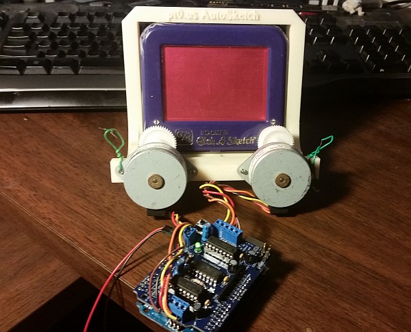
I took a Pocket Etch-A-Sketch that I found in a thrift store, added a pair of gears from a disassembled printer, and mounted it in a 3D printed frame that I designed in Google SketchUp. I then mounted two stepper motors to the frame, and connected them to an Adafruit motor control shield mounted on an Arduino Uno.

hardware_sm

The overall hardware setup, showing the custom frame and the Arduino+motor shield combination. (The Arduino Uno is hiding under the motor shield.)

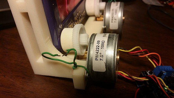
A close-up of the gear mechanism and stepper mounting. (Click for larger.)

A close-up of the gear mechanism and stepper mounting. (Click for larger.)

Here is the Arduino sketch to run everything. (You’ll need the stepper motor library from Adafruit, as well.)

Here is a video of the AutoSketch doing its thing…

Posted in Arduino, C, Coding, Digital, Nostalgia, Toys | Tagged , , , , , | Leave a comment

Components: LEDs

Just about every electronic device produced in the past twenty years or so uses one or more light-emitting diodes (LEDs). They are typically used as indicators (for power status, low-battery warnings, caps lock and number lock on keyboards, etc), but are also sometimes used to provide lighting (display backlights, “flash” lighting on digital cameras, as flashlights, etc.)

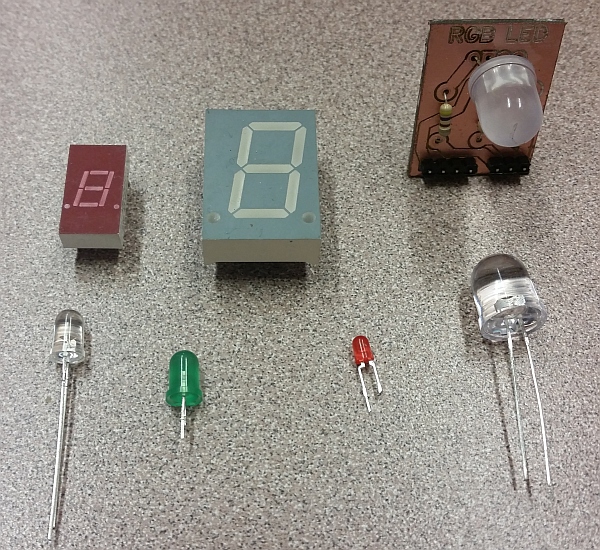
An assortment of LED types.

An assortment of LED types. (Click for larger)

LEDs, in terms of light produced per watt consumed, are many times more efficient than incandescent light bulbs. They generate almost no heat, so nearly all of the power they consume goes directly into producing light. Because of this and other factors (for one thing, they’re extremely reliable when properly used), they have increasingly been used as replacements for incandescent light bulbs for indication and illumination.

If you look closely at modern traffic lights, you might notice that they are made up of a collection of dots, rather than a single glass lens. In place of a light bulb drawing hundreds of watts, a couple dozen LEDs do the same job while using far less power and requiring far less maintenance. Brake lights and tail lights on cars are also good candidates for LEDs, since reliability is important for those applications.

LEDs are also relatively inexpensive: a red or green indicator LED typically costs just a few cents when purchased in bulk. More exotic LEDs can cost a few dollars or more — with the price increasing greatly as the power increases (there’s still not a huge market for really high power LEDs, and they’re somewhat tricky to manufacture, so the economy of scale isn’t quite there yet.)

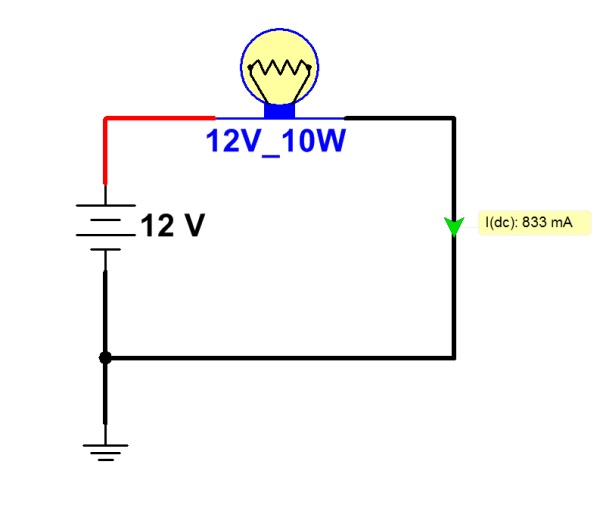
Using LEDs in a circuit is somewhat trickier than simply using a light bulb — although not much. A light bulb is basically just a low-value resistor whose resistive element gets hot enough to glow. They are, to some extent, self-regulating: a light bulb’s resistance increases as it gets hotter, limiting current flow through it somewhat. Given a light bulb of the proper voltage rating, it can simply be connected across the terminals of a battery or power supply.

An incandescent lamp circuit

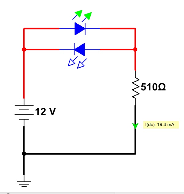
LEDs, on the other hand, require a bit more finesse. First of all, they are diodes — which means that they only allow a significant amount of current to pass in one direction. The cathode of the diode (typically, the shorter lead on the LED package) must be connected to the negative side of the power source. Otherwise, no current will flow.

The forward-biased LED conducts current; the reversed-biased one doesn’t.

In addition, diodes (including LEDs) always have a characteristic “voltage drop.” A simple way of understanding this is that the diode will “try” to limit the difference in voltage across its terminals to no more than this “voltage drop.” It does this by lowering its effective resistance as the amount of current increases (see “Ohm’s Law”), so that the voltage drop remains nearly constant.

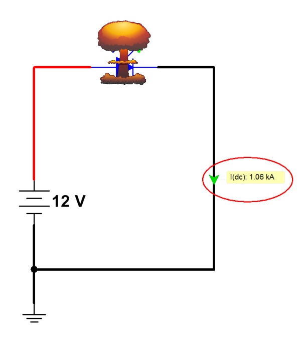
The problem is that too much current will burn out the diode. If an LED were connected across a pair of C-cell flashlight batteries (which produce roughly 3V in series), the voltage would be significantly more than the LED “wants” to see. It would lower its resistance until the voltage drop across the LED matched this built-in limit. By this time, the current flow would be so high that the LED would get very hot and quickly burn out with a brightly-colored flash. (If you’re lucky, you might even get to see the Magic Blue Smoke escaping. Once the Magic Blue Smoke is gone, the component is ruined.)

Without a current-limiting resistor, the LED will allow too much current to pass, and will be destroyed.

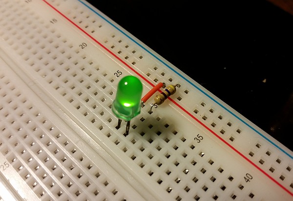
The solution to this is to put a resistor (typically 470 ohms) in series with the LED. This gives the rest of the voltage drop somewhere to go, and limits the current in the circuit to a value the LED can handle (typically 20mA or so, for a standard 5mm LED.) With the addition of a resistor (about 1 cent, in bulk) an LED can make a good, easy-to-use indicator for a circuit.

An LED on a breadboard, with a 470-ohm current-limiting resistor. (Click for larger.)

To calculate the correct size of the resistor, check the LED data sheet for the correct current that should flow through the LED. Then find the typical voltage-drop value from the datasheet (usually larger for blue and white LEDs; smaller for red LEDs). With these two values (voltage drop and current), you can calculate the correct series resistor as follows:

R = (V_t - V_led) / I_led

This calculation works by determining what the voltage drop should be across the resistor (that is, the total voltage minus the LED’s voltage drop per the datasheet.) This is divided by the current that should flow through the LED, to give the required resistance. (Remember Ohm’s Law?)

When connecting more than one LED (such as in a seven-segment numeric LED display), it’s best to provide a separate resistor for each LED. That way, the brightness of the LEDs remains constant regardless of how many LEDs are lit at one time. With all LEDs sharing a single current-limiting resistor, LED brightness will decrease if more than one is lit at a time.

Posted in Building blocks, Components, Electronics, Fundamentals, HOW-TO | Tagged , , , , , , , , , | Leave a comment