The EBCs of BJTs

BJTs (Bipolar Junction Transistors) are inexpensive, reliable, relatively easy to use, and very useful. Here’s what you need to know in order to use them as a simple switch.

A BJT is, essentially, a current-controlled current source. In general, the current flowing into one pin is controlled by a smaller amount of current flowing into another pin. In this way, the transistor can act as a current amplifier

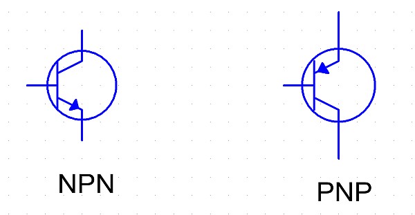
There are two types of BJTs — NPN and PNP. These refer to the order of doped silicon layers: negative, then positive, then negative, for an NPN transistor, and the reverse for a PNP.


NPN: "Not Pointing iN"

Schematic symbols for NPN and PNP transistors.

The three pins on a BJT are the emitter, the collector, and the base. The way I remember which is which is that the emitter emits (into the device) whatever type of carriers (holes or electrons) are described by the transistor type. NPN? Electrons are negative, so they’re emitted by the emitter. PNP? Holes are positive, so the emitter emits those. The other right-hand-side pin, where the carriers are collected, is the collector.

The central pin is the base. This is where the controlling current flows into (NPN) or out of (PNP). (Note: I use conventional current notation, with current flowing from positive to negative.)  The thing to remember is that the emitter-base junction is a diode, and therefore requires current limiting (just like an LED does.)

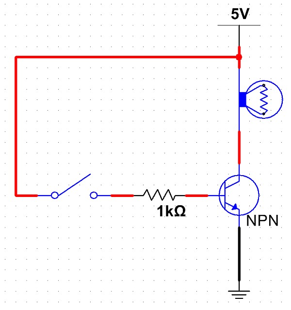
To use a NPN transistor as a switch, it’s easiest to use it to “ground” the load to turn it on. Suppose your load was a lamp. Tie one end of the lamp to the positive voltage rail, tie the other to the collector of the NPN, and tie the emitter of the NPN to ground. Now, flowing a small current into the base of the NPN will cause the NPN to conduct a potentially much larger current from the collector to the emitter, grounding the lamp’s negative terminal and completing the circuit.

NPN_switch

PNP transistors are used similarly, except that they are typically used to switch the high side, and current flows out of the base, not in.


Posted in Analog, Building blocks, Components, Electronics, HOW-TO | Tagged , , , , , , , | Leave a comment

Components: Servos

Do you speak Servo?

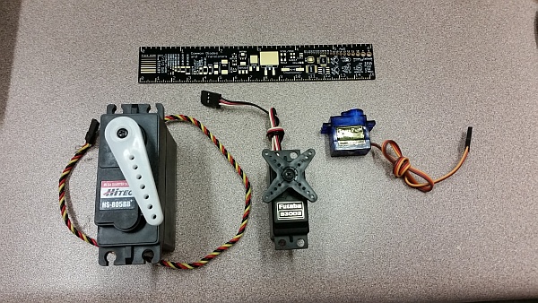
2014-10-31 16.51.15_sm

Various standard servo motors (about 180 degrees movement each). Click for larger.

Servo motors (both positional and continuous-rotation) are useful devices. Provide power, ground, and a relatively simple control signal, and the servo’s onboard circuitry handles all of the motor-control tasks, including a closed-loop feedback system to ensure the servo maintains the correct position or speed.

One nice thing about servo motors is that they are easily controlled by a microcontroller with no additional control or current amplification circuitry needed. Constant DC power (typically, 5V-6V) is applied to the servo, and a control signal is provided to the (high-impedance) control line. One microcontroller, depending on application specifics and processor speed, can control as many as a couple dozen servos.

In addition to traditional servos and continuous-rotation servos, small, efficient, and powerful DC brushless “outrunner” motors have recently become popular in many applications such as electric RC aircraft and quadrotor flying drones. Outrunner motors are essentially three-phase AC motors, driven by a custom controller. Conveniently enough, these controllers usually use the standard servo protocol, as well.

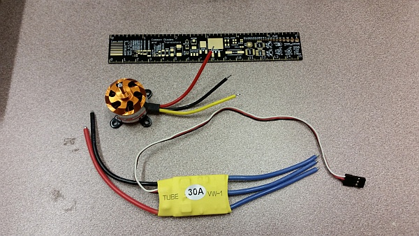
2014-10-31 16.52.06_sm

A brushless DC motor and its electronic controller. The controller receives control commands as if it were a servo motor, allowing existing servo motor microcontroller libraries to be easily adapted to control these motors. (Click for larger.)

In a nutshell, servos and similar devices are controlled by the following signal type:

  • 5V TTL (5VDC high, 0VDC low);
  • High impedance input, easily driven directly by logic;
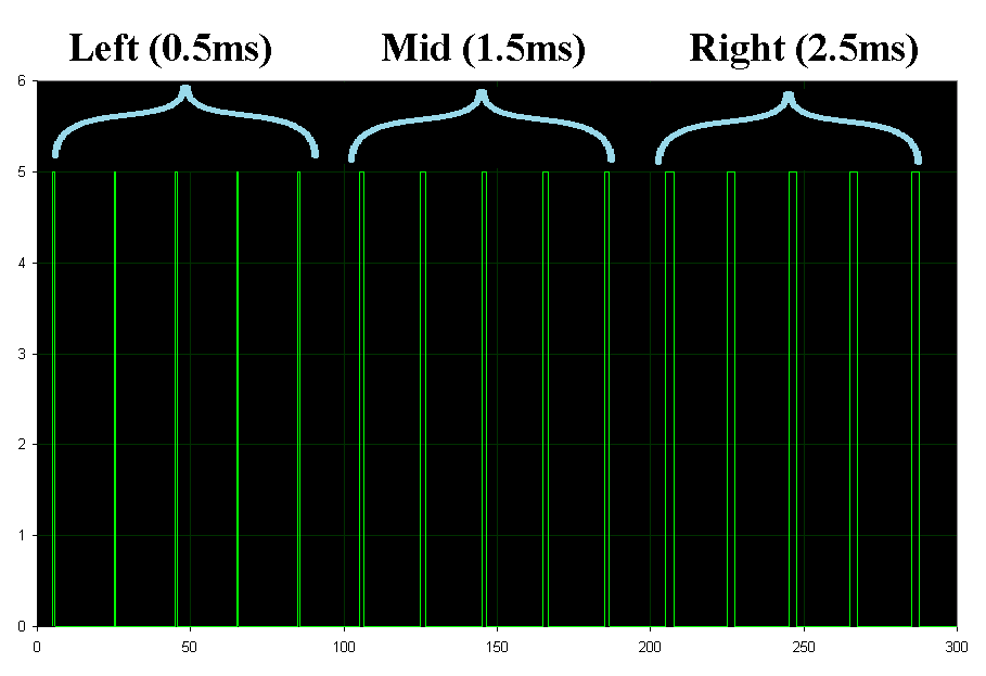
  • 20ms (50Hz) period pulsed input;
  • ~0.5ms — ~2.0ms pulse width (varying the pulse width provides the control variable.)
Pulses to control a servo. Five 0.5ms pulses command full movement in one direction; five 1.5ms pulses command movement to the center; and five 2.5ms pulses command movement in the other direction.

Pulses to control a servo. Five 0.5ms pulses command full movement in one direction; five 1.5ms pulses command movement to the center; and five 2.5ms pulses command movement in the other direction.

One pitfall when working with servos is to think of this signal as a PWM cycle, and calculate servo position based on the duty cycle of the pulse. While technically correct, the “duty cycle” only varies from roughly 1% to 4% when ranging over the entire valid control input range of the servo. A duty cycle of 25%, for example, does not correspond to 25% power, as it would for a motor driven directly by a PWM signal. Rather, a 25% duty cycle pulse train would probably not be understood by the servo controller as a valid signal at all. It’s best to think in terms of pulse width, since changes in pulse width (within a small range) correspond to changes in servo behavior. Even the long 2.5ms pulses are still only 12.5% “duty cycle.”


Posted in Components, Digital, Electronics, HOW-TO, Robotics | Leave a comment

FreePCB Arduino Shield Template

Having been too busy / lazy to sit down and learn Eagle CAD or another “real” PCB program, I’ve been using FreePCB to make all kinds of PC boards on the LPKF board plotter at work.

With our increasing use of Arduinos (we’ve been using them in Senior Design projects for several years now, and are starting to teach introductory programming with them), we will almost certainly need to design Arduino shields in the near future.

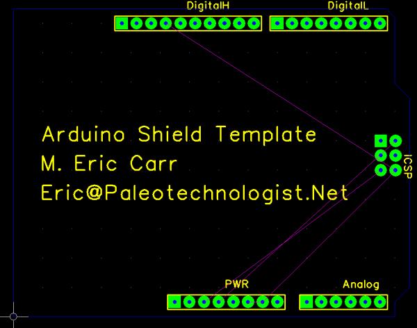
Having looked online and not found an Arduino shield template for FreePCB, I decided to make one.

(Screenshot of template in FreePCB)

The template, rendered in FreePCB. (Click for larger.)

Here is the FreePCB template file. Remember to save a copy before you modify it with the components and traces for your design.

“Share and enjoy!” (CC:BY-SA)


Posted in Arduino, Design, Digital, Electronics, Resources | Tagged , , , , , , , | Leave a comment

User Interface Done Right

Advances in technology often make possible new, more efficient ways of doing things. This can certainly make our lives easier and more enjoyable. As with any change, however, there can be drawbacks. The operation of new devices is not always intuitive to users who have never seen it before. Novel devices should be designed with a naive user in mind: the device should teach the user how to use it — ideally, with little or no effort on the part of the user. This advice is especially relevant in situations when the use of new technology is forced upon users, such as in public restrooms. Infrared towel dispensers, which require the user to perform a kind of modern-day rain dance in order to obtain a towel, are increasingly prevalent. The benefit is that you don’t have to touch the dispenser to get your towel — but for someone who has never seen one before, they can be confusing at first. Sometimes, however, a small change in operation can make a device a lot more intuitive to use. A local community college recently installed touchless towel dispensers in its restrooms. These dispensers, however, extend a towel right away, replacing it immediately when it is taken. Even if a user hasn’t seen one of these before, they will probably understand that they are supposed to take the towel.  When they do so, the dispenser replaces it. Now the user knows how the process works, without ever having to figure anything out! 2014-08-07 17.32.55_sm

Posted in Design, Digital Citizenship, User Interface Design | Leave a comment