Components: Resistors

One of the most basic electronic components is the resistor. At first, these components don’t seem very useful; their function is to restrict (or resist) the flow of electrical current through a circuit. With today’s emphasis on efficiency, this seems pointless. However, various effects of resistors’ behavior make them important electronic components — and one of the easiest ones to understand. If you plan on building electronic circuits of more than the absolute minimum complexity, you will eventually need to understand and use resistors. Fortunately, this is easy.

Understanding resistors starts with an understanding of Ohm’s Law. (Voltage is equal to Current times Resistance. Follow the link above for a more in-depth explanation.)

Resistors come in many forms; perhaps the type most commonly used by hobbyists is the 1/4-watt, through-hole fixed-value resistor. These are axial components (meaning they have two connecting wires, initially 180 degrees apart), and are about 2mm in diameter at their thickest part (they would fit inside a typical drinking straw if not bent.) The example resistor shown below is of this type.

Typically, fixed-value through-hole resistors will have four color bands, which specify what the resistor’s nominal value and tolerance (margin of error) is. Here is a chart to help decode what the colors mean:
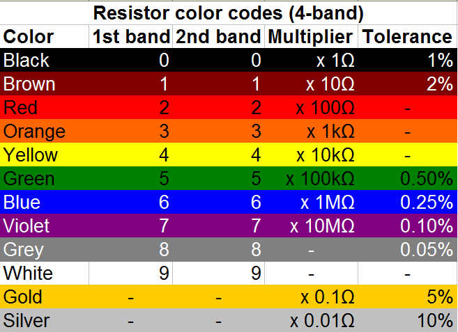
A well-known mnemonic (which I did not write) is: "Bad Boys Ravish Our Young Girls, But Violet Gives Willingly."


Here is an example of how these codes would be read on a garden-variety 1-kilohm (or “1k”) resistor. (Click on the image below for a higher-resolution version.) Reading the bands from the left, the brown band represents 1, and the black band represents 0. Putting these together gives “10” for the base value. (The first band is almost never black, except in the unusual case of a “zero-ohm” resistor: a single black band, otherwise known as a “wire.”) The third band is the multiplier band; red signifies multiplication by 100, making the total value 10 x 100 = 1,000 ohms — or “1k.” The 4th band is the tolerance band; gold signifies that the true resistance value of this component should be within 5% of the stated value (950 to 1,050 ohms).
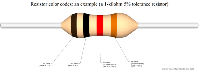
A 1-kilohm resistor (10 + 0, times 100, is 1000 ohms). The wire is roughly as thick as a pencil lead. Click for larger.

Resistors are used for many tasks in electronics. Without going into too much detail, here is a sampling of some of their many uses:

  • Current-limiting: a 470-ohm or similar resistor is typically needed in series with an LED, in order to limit the amount of current flowing though the LED.
  • Voltage-divider use: Two or more resistors can be used to “divide” a voltage proportionately to the total resistance. For example, if a 2k and 3k resistor were placed in series between a 5V supply and ground, the voltage between the two would be 3V (if the 3k resistor was connected to ground) or 2V (if the 2k resistor was connected to ground).
  • As a “pull-up” or “pull-down” resistor: The voltage on an unconnected (or “floating”) wire is affected by nearby electrical fields, and tends to pick up a lot of noise. If such a wire is connected to the input of a digital circuit, the results will be unpredictable. A fairly high value resistor (1k is typical) is used to “pull up” the voltage to a logical high voltage (typically 5V or 3.3V) or “pull down” the voltage to ground. A switch can then safely be used to connect the input to the other value, without shorting anything out (the current through the resistor is small enough to be negligible.)
  • To measure current: A small, precise resistor (or strip of wire of known resistance) can be used to measure current passing through it. Since Voltage = Current times Resistance (V=IR), a current passing through a known resistance will produce a voltage differential directly proportional to that current. Passing, say, 3 amps through a 0.01-ohm shunt will produce a voltage of 30mV across the shunt. This can be measured by a voltmeter to infer the amount of current flowing through the shunt.
  • To discharge a capacitor: Some capacitors can hold a large amount of energy for a long time. When high-power equipment is turned off and the supply cord disconnected, it is safest if any capacitors can be automatically discharged. A “large” resistor (meaning one with a large resistance value, such as several kilohms or megohms) is permanently wired in parallel with the capacitor. When the power is turned off, this “bleeder” resistor safely discharges the capacitor.
Posted in Analog, Components, EET201, EET205, Electronics, Science | Tagged , , , , | 1 Comment

Paleotech Projects!

Learning about electronics (and technology in general) is, for me at least, about building things. It’s nice to learn the theoretical background behind how a circuit works, but sometimes getting a good intuitive understanding means putting components together into a real, working circuit.

I’m currently working on developing several projects to be published here. The idea behind each one will be to allow anyone interested to build them, and learn about various concepts related to electronics in the process. The plans will be open-source and published under the Creative Commons “CC BY-NC-SA” license, meaning you’re free to copy the plans (with attribution) for noncommercial purposes, and modify them as long as you share your modifications. If you’d like to use one or more projects in a commercial venture, please contact me first. The idea is to help more people get interested in electronics and to teach basic electronics concepts; if you have an idea for a product that could help with that, I’d like to hear about it.

The projects are categorized according to a rough “level” scheme, to provide an idea of how complex or difficult a particular project is. Here is an overview of what is meant by each level:

  • Level 1: A quick project (maybe an hour or less) requiring basic tools and equipment. An example would be experiments connecting light bulbs in series and parallel.
  • Level 2: A short project (perhaps an evening) requiring basic to moderate-level tools and equipment. An example would be a 555-based LED blinker or perhaps a very straightforward Arduino project.
  • Level 3: A moderate-length project (maybe a weekend or two) requiring some specialized equipment (oscilloscopes, programmers, etc) depending on the project. Simple PIC projects would generally be Level 3.
  • Level 4: A significant project (perhaps a few weeks) requiring extensive electronics knowledge and/or specialized equipment. Examples would be the GPS puzzle box project and the DrACo/Z80.
  • Level 5: Extremely complex projects requiring weeks to years to complete. (Basically, anything too complex to qualify as Level 4.) An example would be GPS-enabled autonomous aircraft.

The projects have their own page, in addition to being featured as regular articles as they are created. Comments and questions are welcomed — post in the comments or send me an email (“eric” at this domain) if you’re not a spambot.


Posted in Digital Citizenship, Electronics, HOW-TO, Projects, Science | Leave a comment

I/O, I/O, It’s Out The Port We Go…

Android devices are great things. I’ve been enjoying my Epic 4G ever since I got it (on release day) last August. There are lots of apps for it — and even a modern dialect of BASIC. I’m continually finding out new things to do with it, from playing Augmented Reality games to enjoying interesting music-meets-the-visual-arts applications, to going for a quick virtual flight.

I’ve even recently started learning Android development. Even though Java is necessarily involved in this process, it’s been fun. One thing has been missing, though — the ability to connect with embedded devices. Embedded system design is a big part of what I do, and I missed the ability to tie applications to external microcontroller-powered devices.

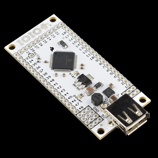
The IOIO board for Android (available from SparkFun) fills this niche nicely. Once you’re set up for Android developing, the IOIO board and accompanying API allows Android devices to electronically interact with the outside world.

In Embedded-Geek-speak, it gives your Android devices GPIO ports.

The IOIO board -- GPIO ports for your Android!

The online documentation for the IOIO board is available here.

Here is a quick walkthrough of what it takes to get up and running with the IOIO board, starting from scratch. Much of this information was distilled from the excellent tutorial available on SparkFun’s site — if you’re already an experienced Android developer, you might want to start there instead, since they don’t bother to cover all of the necessary steps in gory detail. (They do link to everything you need, though.)

To make connecting to the board easier, you will probably want to solder some row connectors to it. I went with a DIP configuration: a 22-pin row down each side of the board. That will allow you to use it with a pair of 830-pin solderless breadboards. (You’ll want to either use a decent temperature-controlled soldering iron with a narrow tip to do this, or bribe a friend who’s good at soldering.) Solder the connectors so they connect to the bottom of the board and point downwards.

Software-wise, you will first need the Java JDK (about 70MB, for Windows).  This is not the same thing as the Java runtime environment (JRE), which I won’t link to here to avoid confusion. The JDK allows you to actually develop Java applications. Download and install it first. (Make sure you get the version you need for your system — although for some reason, I needed to install the 32-bit version even though I’m running 64-bit Windows 7. You may have to, as well. Go figure.)

Next, I strongly recommend downloading the (classic / Helios version of the) Eclipse IDE, available here. This will help organize development tasks and provide an integrated environment in which to work. There are other IDEs — possibly very good ones — but Eclipse is the one I’m most familiar with, and so I will base this walkthrough on it. (All of these tools are free, by the way.) Download and install Eclipse (again, get the version appropriate for your host OS.)

Unpack Eclipse into a directory where you want it to reside (maybe C:\eclipse for Windows systems, or perhaps on a folder on your desktop, if you plan on using it a lot. I left mine in a folder named eclipse on the desktop.) Eclipse is a portable app, which means that you don’t have to bother with actually installing it (and therefore, tying it to one particular system.) Once unpacked, you can run it directly.

Once you have Eclipse installed, download and unpack the Android SDK (or maybe run the installer exe, for Windows. This is what I did.) Again, put it somewhere safe — perhaps in its own directory off the drive root, perhaps somewhere else that makes sense to you. (You won’t need to access this yourself, although you will specify where the Android development plugin for Eclipse can find it, later.) Note: If you are running Windows 7 64-bit and you installed the 64-bit JDK, you might get a message saying the installer can’t find the JDK. The fix that I found for this was to install the 32-bit JDK, as well.

Once the Android SDK installer finishes, it will give you the option to run the SDK installation manager. Run this and download the whole set of tools (“accept all”). This may take a while, depending on how fast (or in my case, slow) your Internet connection is. (Verizon — where’s my FIOS, guys?)

The final step is to start up Eclipse and install the ADT Plugin. This is an automated installation done from inside Eclipse. Start Eclipse, click on Help, then Install New Software. Click the Add button, and provide this URL:   https://dl-ssl.google.com/android/eclipse/ (The installation guide recommends that you call it “ADT plugin.”)

Once the plugin finishes installing, you’re ready to start developing for Android. Now to set up for IOIO-specific development. Download the “HelloIOIO” example and import it into Eclipse. (Detailed instructions are available on the tutorial page, here.) Next, download the IOIOLib library file and unpack it into the same parent directory where you put the HelloIOIO directory. Click on Project –> Properties, select Android, then choose the appropriate API level for your target device (probably Android 2.x). Add Internet permissions (android.permission.INTERNET under Add -> Permissions), and you’re done.

Run make, and select your Android device as the target. The app won’t do anything interesting right away, since your Android is still tethered to the PC and not the IOIO board. Once the app is in place, disconnect the Android from the PC, power the IOIO board with 12V (they say 5-15V, but I’ve found at least 7V or so is needed), and connect the Android to the USB connector on the IOIO. It should start charging; if not, you may need to increase the charge current value using the potentiometer near the USB port on the IOIO board. Fully-clockwise seems to work reliably for me.

With the Android connected to the board, run the HelloIOIO app and press the button. If everything went well, you should be able to turn the LED on the board on and off. Congratulations — your Android smartphone now speaks TTL!


Posted in Android, Coding, Digital, HOW-TO, Java, Toys | Leave a comment

Buon giorno, Arduino!

I stopped by Micro Center today, and was pleasantly surprised to see that they stock some SparkFun kits and components. Their SparkFun inventory is very Arduino-centric; they carry inventor kits, Arduino Uno boards, and Arduino Pro Mini boards (some assembly required.)

Sparkfun gear at Micro Center!

I picked up an Arduino Uno (it looked like the typical Arduino board I’ve seen online), as well as an SD card “shield” accessory for it. I wanted to see what the difference was between developing for Arduino vs. developing for a stock microcontroller.


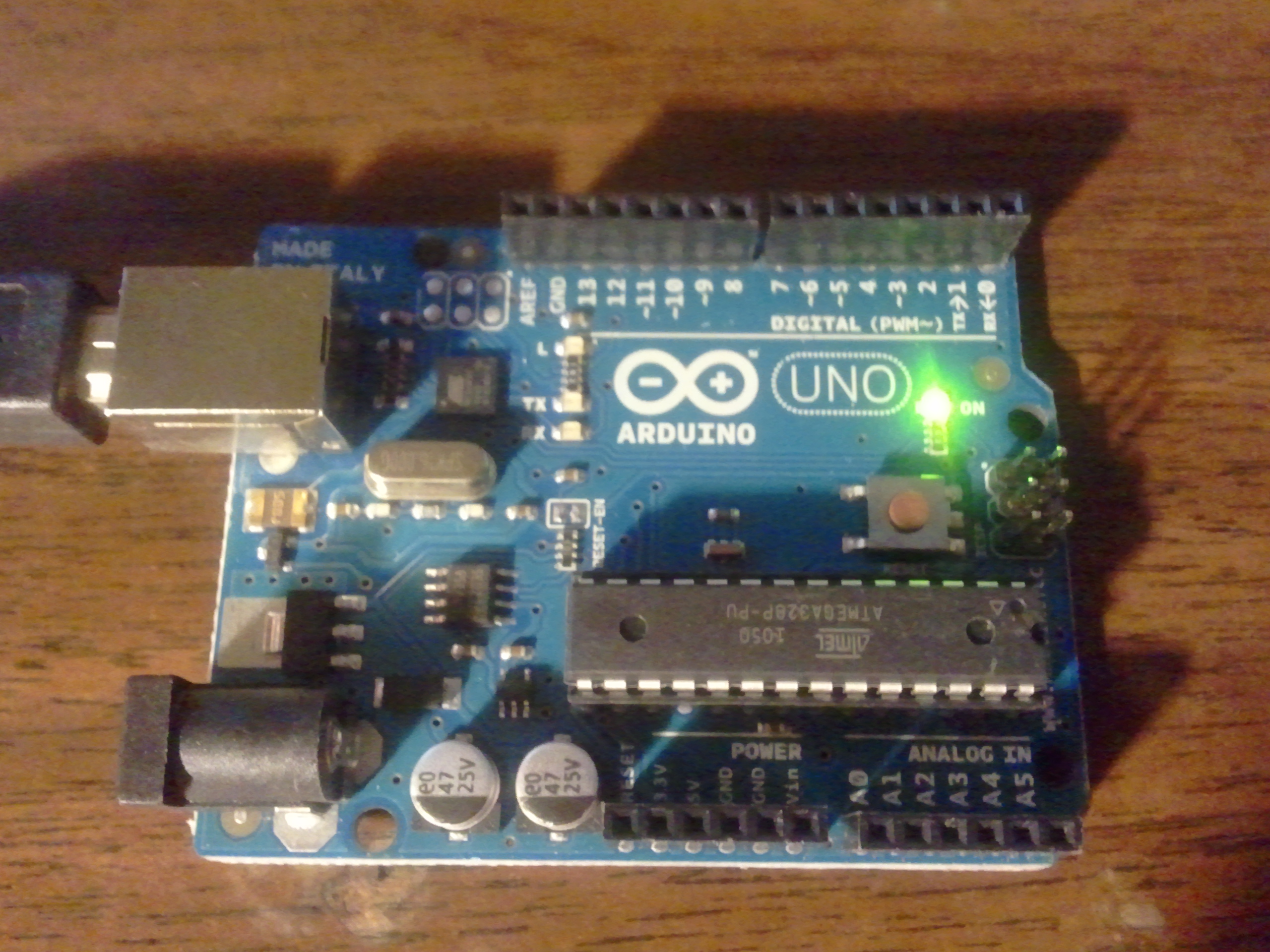
The Arduino Uno -- a basic dev board

It’s insanely easy! To give an idea of just how easy take the typical blink-a-single-LED-on-and-off-once-per-second test program (the embedded designer’s equivalent of “Hello, World.”) Here’s what’s involved (for those using Windows 7):

  • Buy an Arduino Uno board (or make one, if you want — the plans are open source!)
  • Find a USB A-to-B cable, since the board doesn’t come with one.
  • Download the Arduino software (Free, as in speech) here, and unpack it somewhere. (No need to install; it’s portable software!)
  • Connect the board to your PC (it gets its power through the USB cable.) The driver installation process will fail — wait for it to finish.
  • Install the driver manually (it’s in the drivers subfolder wherever you unpacked the Arduino software.) Note which COM port number it chooses (or move it as desired).
  • Run the Arduino software.
  • Click File->Examples->Basic->Blink. This will load the “Blink” example.
  • Click the “Upload” button to upload the “sketch” (program). The yellow LED on the board will start blinking. You’re up and running!

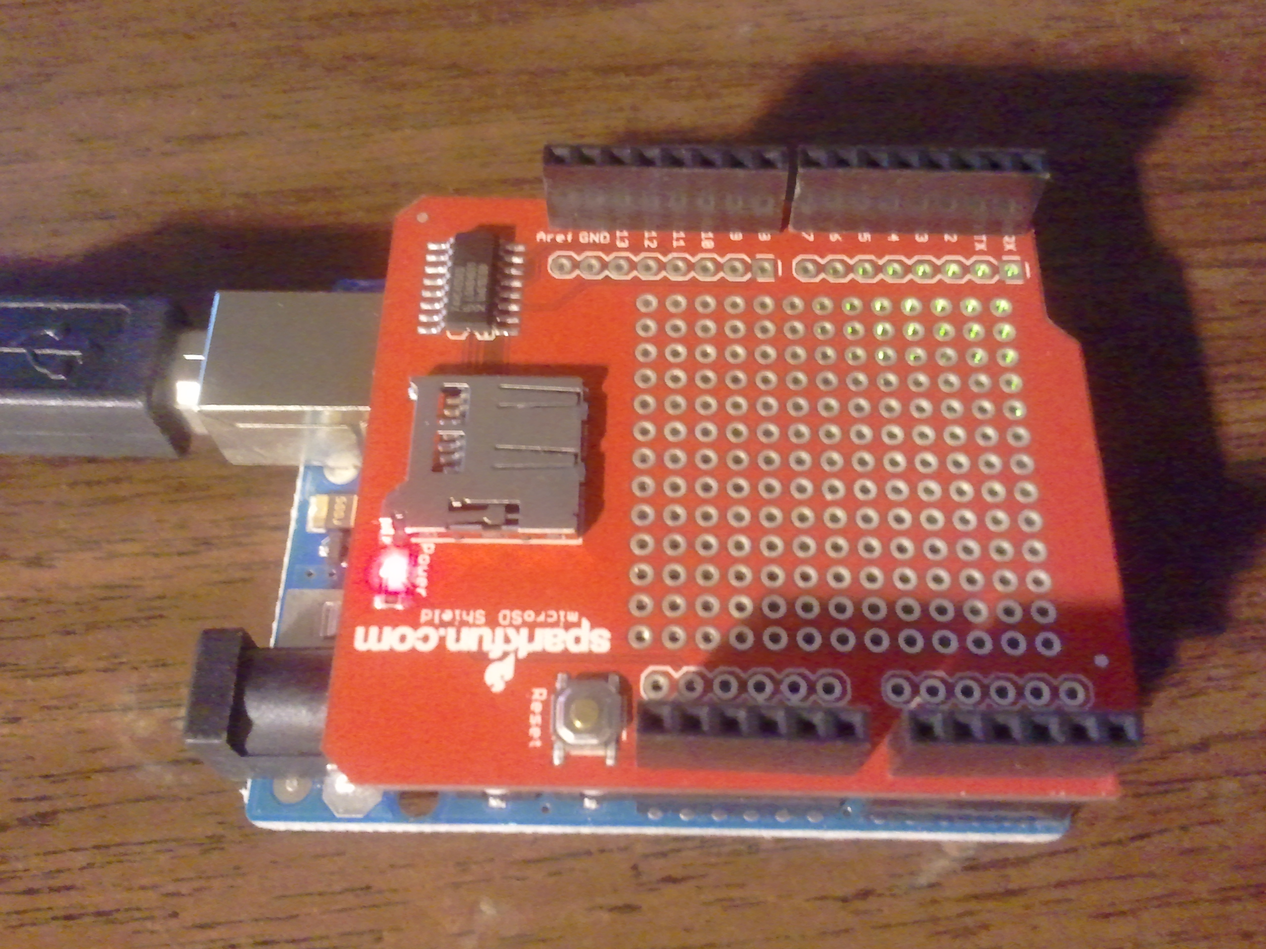
Opening, reading, and writing files stored on a MicroSD card is nearly as easy, if you have the MicroSD card “shield” (accessory board). This assembled in about ten minutes (a question of soldering on four rows of header pins), and plugged right in to the main Arduino Uno board, piggyback-style. After loading a provided SD card example, the board was able to read and write a “test.txt” file. Modifying this to write a list of Fibonacci numbers to a file called fibonacc.txt (apparently filenames have to conform to the old 8×3 format) was very straightforward, too. Suddenly, megabytes or gigabytes of storage are available for embedded projects!


A MicroSD card "shield" on the Arduino Uno

So, in conclusion, working with Arduino boards is pretty cool! About the only drawback I’ve found so far is an increased appetite. For whatever reason, I tend to associate the Italian language with good food: tortellini; calzone; pizza; formaggio parmigiana, mozzarella è provolone etc. Linguistically, for me, it’s a short hop from “Arduino duemilanove” (“Arduino 2009”) to imagining all kinds of culinary delights. The Italians certainly know how to cook. Apparently, they’re also pretty good at designing dev board systems!


Posted in Arduino, C, Coding, Digital, Electronics, HOW-TO, Toys | Leave a comment