In addition to my interest in electronics and computing, I’ve always found aircraft fascinating. Some of it is the still-magical idea of making something that can lift itself off the ground and fly, supported only by air. Some of it is also the natural inclination, upon seeing an airliner, truck, or freight train, to wonder where it came from and where it’s going. For engineers, I suspect that a lot of the fascination comes from our love of systems of all kinds — and figuring out how they work.
Planespotting (basically, “collecting” aircraft by identification number) is a fun pastime, and can be a good way to learn about different types of aircraft. (A Cessna 152 and Boeing 747-8 are both fixed-wing aircraft, but that’s about the only similarity.)
With all of the recent fuss about National Security (gotta protect our Precious
Bodily Fluids, after all!), some traditional planespotting techniques are frowned upon by the Security Theater types. Hanging around the local airport with a pair of binoculars is likely to get you some suspicious looks if you’re white, and thrown into jail if you’re not.
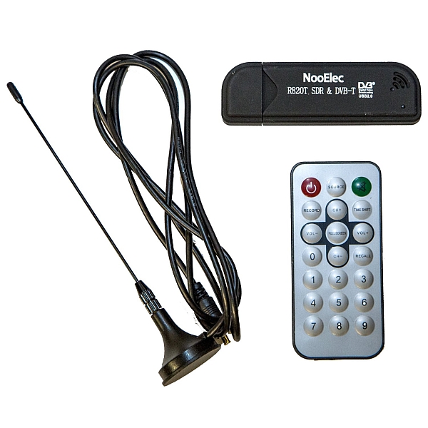
Fortunately, it’s 2015, and we have some really amazing technology at our disposal. For about US$22, you can purchase a USB-based digital TV receiver, which can be easily reconfigured to be a general-purpose SDR receiver, covering roughly 25MHz to 1750MHz. This covers a lot of interesting content, including FM broadcast radio, several Amateur Radio bands, several aviation-related bands (VORs, VHF comm frequencies, etc.)
It also happens to cover the 1090MHz ADS-B band. ADS-B is a clever extension of the idea behind GPS: Aircraft with GPS receivers (which is basically all aircraft, these days) know their exact position (in terms of latitude and longitude) at all times. If they were to broadcast this in a controlled manner, other local aircraft (and ATC) could listen for these transmissions and draw a map of where nearby aircraft are, adding an extra layer of collision-avoidance safety.
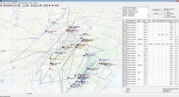
Since aircraft positions are broadcast in the clear, anyone with the right (inexpensive) equipment can pick up these signals and plot a map of where local aircraft are. Here is a map of several hours’ worth of traffic through the Philadelphia area:
Each plane is generally identified by registration number and often flight number, allowing online lookups of where it came from and where it’s going. By connecting with an online database of aircraft positions, data can be shared with anyone with a web browser. With thousands of inexpensive receivers throughout the world, aircraft could potentially be tracked anywhere that reliable Internet connections exist.
It’s easy enough to get started. All you need is a reasonably fast computer (anything built in the past few years is probably fine), an SDR dongle, and some software. The process goes like this:
- Buy a SDR dongle, plug in its antenna, and connect it to your computer. (The drivers don’t like some modern USB3.0 ports, so you may have to try a new port if the SDR# software doesn’t recognize your device.)
- Install the SDR# software. (Their “Airspy” hardware is not needed if you have the inexpensive dongle from Amazon, but it looks to be a nicer, significantly higher-spec version of the same thing.)
- Use the “Zadig” driver installation program included with the SDR# software to install the SDR driver for the dongle. (There are instructions on the SDR site.)
- Open the SDR# software to test your setup. Receiving a local FM broadcast station should be a good test.
- Close the SDR# software and run ADSBSharp.exe (included with the SDR# software.) Hit the Start button to start it running.
- Download, install, and run the ADSBScope software from sprut.de .
- In ADSBScope, go to other->Network->Network Setup to set up the network for ADSB# (port 47806).
- Click Other ->Network->”RAW data Client active” to start the network client.
Happy digital planespotting!


