Pointers in BASIC

BASIC, as Rodney Dangerfield would have said, “don’t get no respect.” Even when using modern dialects like FreeBASIC, which allow custom user types, modern-style functions and subroutines, encapsulation, and more, there’s still very much a “Real Men Program In C” attitude.

C is deservedly famous and influential, of course, but it’s often tedious to write small, proof-of-concept programs in C. If a new idea about, say, cellular automata strikes you, it’s very easy to write a few lines of BASIC code and be testing it — in full-color HD.

But still, C proponents say, it’s a “toy” language. It doesn’t have pointers or linked lists or all that.

Except — it does. In FreeBasic, at least, the familiar malloc() and sizeof() functions are available, and memory truly can be dynamically allocated, deallocated, and manipulated as pointers.

Here is a short example that demonstrates creating and printing out a simple linked list in FreeBASIC. Memory is dynamically allocated and user type fields are accessed with the -> operator, just as in C.

'Pointers in FreeBASIC
 'Example: Create and print out a short linked list

'M. Eric Carr / Paleotechnologist.Net
 'Contact: eric (at) the above domain

'Define a simple user type
 type listItem
 payload as double
 link as listItem ptr '"next" is a keyword in BASIC; we can't use it.
 end type

dim as listItem ptr head, current
 dim as integer n

'Teach FreeBASIC about NULL
 const NULL = 0

'Set up the first item in the list manually
 head = allocate(sizeof(listItem))
 current = head
 current->payload = 0
 current->link = NULL

'Use a for loop to add nine more items to the list
 for n=1 to 9
 'Starting conditions: current points to last item in the list.
 current->link = allocate(sizeof(listItem))
 current = current->link
 current->link = NULL 'For safety
 current->payload = n^2
 next n

'Read them back using a while loop, looking for the NULL at the end
 current = head
 while current <> NULL
 print current->payload
 current = current->link
 wend

'Done. Wait for a keypress before exiting.
 sleep

(Don’t tell the use-C-or-die types, but FreeBASIC can use inline x86 assembly, too.)

Posted in BASIC, C, Coding, HOW-TO | Leave a comment

DIY Ionic charging

The Fitbit Ionic is a neat little device, capable of tracking various different exercises as well as providing continuous heart rate monitoring and sleep quality tracking. It is quite well-connected as well, with WiFi, BlueTooth, and NFC capabilities. It can stream music to Bluetooth headphones, sync exercise data over WiFi, and pay for your snacks via NFC.

The battery life is better than I expected, too. It will run for several days of typical use without charging. If I don’t use the GPS tracking feature much, it can sometimes go roughly a week between charges. It even sends you an email when it’s low on energy. Welcome to the future.

The one drawback, of course, is that (being waterproof) the Ionic uses a proprietary MagSafe-like connector for charging. And naturally there’s no information readily available about what pins are what. So if your Ionic’s battery is low and you don’t have its charging cable handy, you’re pretty much out of luck.

Time for some detective work.

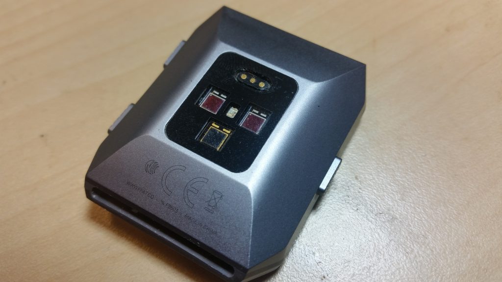
The back of the Ionic. The three gold pins are for the charging cable.

I knew that the charging connector was symmetric; it will work in either orientation. So the two outside pins must have the same function. This, with the fact that the charging cables don’t look like they contain more than just wires, means that, in all likelihood, either the center pin is ground and the outer pins are 5V, or the other way around. If I were designing a watch like this, I’d go for one 5V pin in the center and two ground pins. Let’s try that, I figured.

So I hacked together a small breadboard-based adapter and connected it to a current-limited lab power supply. (The current-limited part is important: if you get the polarity wrong and forward-bias a protection diode, you don’t want your power supply dumping three amps of current through it. That’s how the magic smoke gets let out. With the current limiting, the supply will back off on the voltage if too much current is flowing. This gives you time to disconnect it before anything gets too warm.)

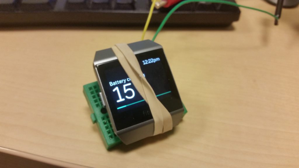
I limited the power supply to 300mA and gave it a shot. With a little adjustment to get it to sit on the pins properly, it works, drawing about 180mA at 5V.

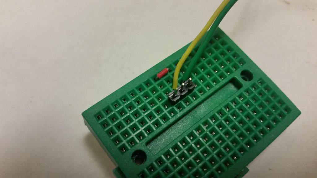
Details of the connections. The outer two pins are tied together and to Ground. The center pin is 5V.

The Ionic, less its wristband, on its makeshift charger.

The adapter itself is straightforward: Three standard row-connector pins, with the outer two bent slightly inwards to match the Ionic’s connector pitch. The outer two are connected together and to Ground (black, on a USB cable); the center pin is connected to a 5V supply (red, on a USB cable).

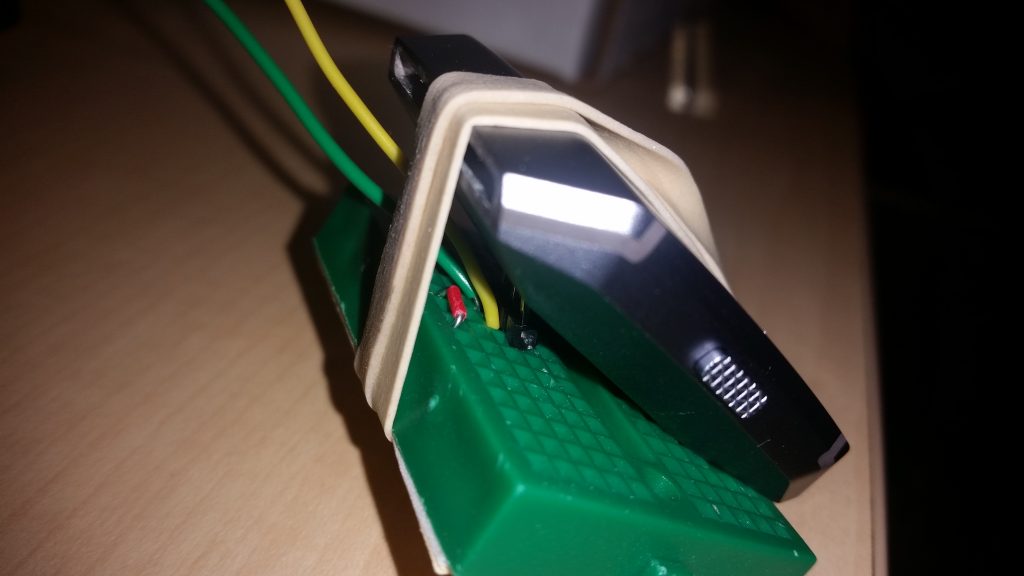
The Ionic on the makeshift charger, showing some of the connections.

Disclaimer: Use this technique at your own risk; this is a hack, not an engineered solution. It worked for me, and properly implemented, should work for anyone, but will certainly void your warranty if you get it wrong (and maybe even if you do it right.)


Posted in Hacks, HOW-TO, Power, Reverse Engineering, Toys | Leave a comment

NeoPixels

“Civilization advances by extending the number of important operations which we can perform without thinking about them.”

–Alfred North Whitehead

More interesting components make for more interesting devices. This is certainly the case with one of Adafruit Industries’ latest creations — the NeoPixel.

NeoPixel (breadboardable version) (Image: Adafruit.com)


The idea behind NeoPixels is both simple and brilliant. Make a true-color RGB LED as easy as possible to drive with a microcontroller. Normally, in order to get full color from a RGB LED, you need to send PWM signals to the three signal pins. Controlling this on a small microcontroller with limited resources can be demanding, leading to design compromises like using only the eight basic steady-state RGB colors or only flashing the color intermittently, when the processor has nothing better to do.

With NeoPixels, the PWM functionality has been offloaded onto the LED. NeoPixels have a four-wire interface — and that’s counting ground, power, and signal out. Now running a full-color LED only takes one wire, and takes far less of the processor’s attention. Instead of continually monitoring the RGB pin states, the CPU sends a new color whenever it changes, and goes about its business (or goes to sleep) at other times.

Adafruit has an excellent “Uberguide” to everything NeoPixel. Load an Arduino library or two, and two or three lines of code later, you have color. Interfacing with a PIC is almost as easy once you have a few bit-banging routines written.

NeoPixels can be daisy-chained, too. The signal-out pin of one connects to the signal-in pin on the next one. There’s no practical limit to the number that can be chained this way, if you don’t mind the latency and distribute power and ground. Once a NeoPixel has received its twenty-four bits, it sends all subsequent bits down the line. So the first three bytes sent control the first NeoPixel in the chain, the second three bytes control the color of the second, and so on. (The NeoPixels don’t know and don’t care if anyone is listening downstream, which makes interfacing easy but doesn’t allow for verification.)

They come in single units, strips, rings, panels, and now they’re even available in 5mm and 8mm through-hole.

I love living in the future.

Posted in Arduino, Components, Design, Digital, Electronics, PIC Microcontrollers, Reviews | Leave a comment

2D, 3D printing

A 3D printer is, ultimately, a gantry system. It normally uses this setup to position a plastic extruder to make parts — but it can be used for many other tasks, as well.

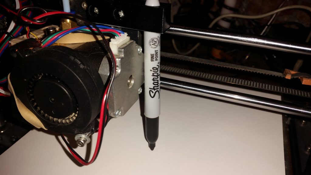
As a preliminary test of this functionality, I printed a bracket to hold a Sharpie, to try drawing with the printer in 2D. With the right G-code commands, the printer can be turned into a plotter. (It should even be fairly straightforward to arrange a pen-swap mechanism; HP had this on their plotters decades ago.)

The Sharpie in place, ready to start plotting.

Before testing with the pen in place, I wrote a custom .gcode file to check the printer’s behavior. If a new file was sent to the printer, would it home itself before printing (which would not work well with the pen mount)? The file consisted of a single command:  G0 X100 Y100 F1200. This is a command to move the gantry to (100,100,Z) where Z is the current, unchanged, Z position.

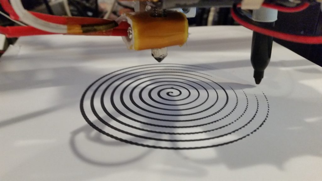
It worked — meaning it didn’t reset the Z position which would crash the pen into the bed — so the next step was to create a more complex 2D G-code file to draw an Archimedes spiral.

An Archimedes spiral, given by R (in mm) = 5*theta/(2*pi). (Click for larger.)
Make sure your pen stays below the nozzle!

Here is a link to the bracket on Thingiverse, if you want to try this yourself.

The relevant G-code command is G0 (with a zero, not o). Here’s the syntax:

G0      Rapid linear move X### Y### Z### E### F### (mm/min)

So, a G-code file to draw a square might look like:

G0 X100 Y100 Z23 F1200 ;Start at (100,100,23) just above the paper
G0 X100 Y100 Z21.5 ;Pen down — your height will vary.
G0 X100 Y150 F1200
G0 X150 Y150 F1200
G0 X150 Y100 F1200
G0 X100 Y100 F1200

Happy plotting!

Posted in 3D Printing, Coding, HOW-TO | Leave a comment